Manufacturing method for machine tool

a machine tool and manufacturing method technology, applied in the direction of process and machine control, program control, instruments, etc., can solve the problems of increasing the cost of cad/cam software, increasing the cost of buying cad/cam software, and increasing the cost of hiring operators, so as to improve the quality of workpieces and reduce production costs. , the effect of simplifying the conventional method

Active Publication Date: 2012-05-17
IND TECH RES INST
View PDF12 Cites 24 Cited by
  • Summary
  • Abstract
  • Description
  • Claims
  • Application Information

AI Technical Summary

Benefits of technology

[0013]Accordingly, in the manufacturing method for a machine tool of the present invention, one or more specific manufacturing areas and corresponding specific conditions are set via a human-machine interface, and the specific condition is used in response to the specific manufacturing area while manufacturing a workpiece, so as to simplify the conventional method that the shape and precision of the workpiece are adjusted by CAD / CAM software or the feeding rate, the rotation rate of the main shaft and the manufacturing program are adjusted by buttons. Hence, the manufacturing method for a machine tool of the present invention improves the quality of workpiece and decreases the production cost.

Problems solved by technology

However, once the shape of the workpiece is more complicated, the single-column input of the CNC program takes more time.
However, the CAD / CAM software is expensive, and the cost must be increased to buy CAD / CAM software and hire operators.
This, however, takes much time and easily results in errors.
However, such adjustment cannot only focus on the defect, and therefore when the defect is overcome to meet the standard, other areas are over standard.

Method used


Image

  • Manufacturing method for machine tool
  • Manufacturing method for machine tool
  • Manufacturing method for machine tool

Examples


Embodiment Construction

[0019]The detailed description of the present invention is illustrated by the following specific examples. Persons skilled in the art can conceive the other advantages and effects of the present invention based on the disclosure contained in the specification of the present invention.

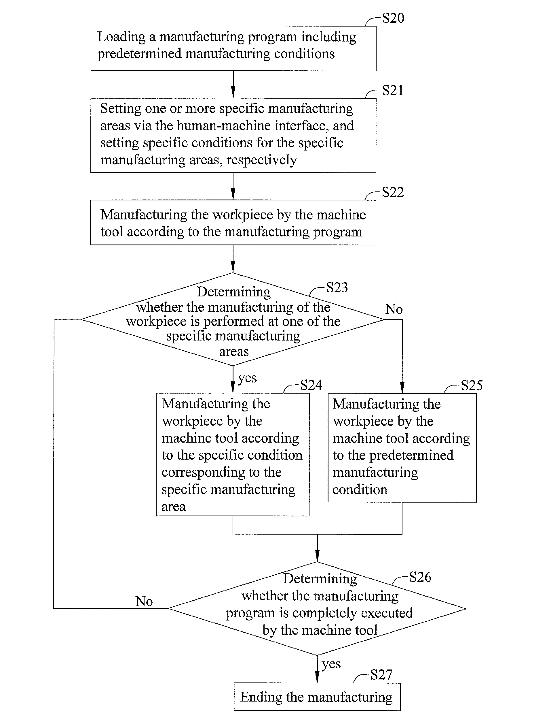
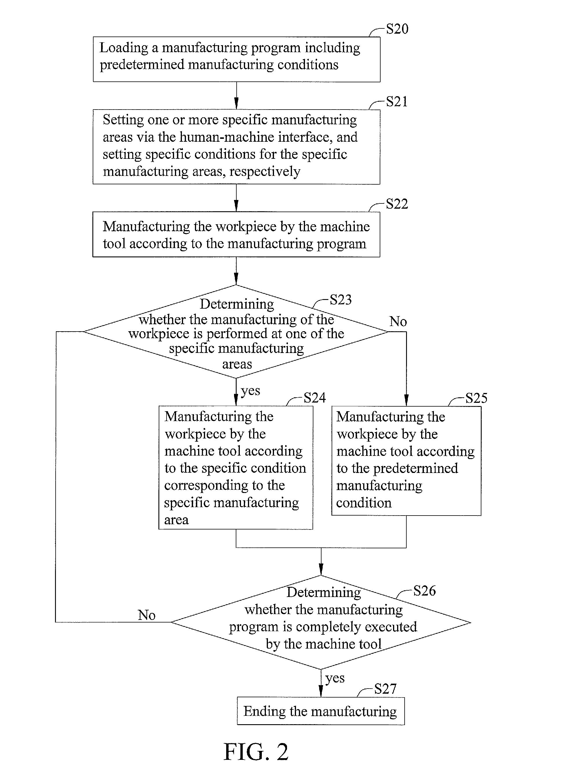
[0020]FIG. 2 is a flow chart showing the manufacturing method for a machine tool according to the present invention. Specifically, the machine tool has a controller for controlling the movement or rotation of a main shaft, which is loaded with cutting means, so as to control the moving path of the cutting means.

[0021]In the step S20, the manufacturing program is loaded by the controller, wherein the manufacturing program includes predetermined conditions, and the controller instructs each shaft to move for manufacturing a workpiece according to the commands of the program. Specifically, the program loaded by the controller includes the predetermined conditions, such as the manufacturing path, the rotati...


PUM

PropertyMeasurementUnit
manufacturing timeaaaaaaaaaa
timeaaaaaaaaaa
shapeaaaaaaaaaa

Abstract

The present invention provides a manufacturing method for a machine tool having a human-machine interface and a program with predetermined manufacturing conditions. The manufacturing method includes (1) setting, via the human-machine interface, one or more specific manufacturing areas of the workpiece and specific conditions for the specific manufacturing areas; (2) determining by the controller whether the manufacturing of the workpiece is performed at one of the specific manufacturing areas; (3) performing the manufacturing of the workpiece under one of the specific conditions corresponding to the one of the specific manufacturing areas via the controller and monitoring continuously the manufacturing status of the machine tool if the manufacturing of the workpiece is performed at one of the specific manufacturing areas; and (4) performing the manufacturing of the workpiece according to the predetermined manufacturing conditions via the controller if the manufacturing of the workpiece is not performed at the specific manufacturing areas.

Description

BACKGROUND[0001]1. Field of the Invention[0002]The present invention relates to manufacturing methods for a machine tool, and more particularly, to a manufacturing method for setting a specific manufacturing area and using a specific manufacturing condition for a workpiece.[0003]2. Description of Related Art[0004]Computer numerical control (CNC) machine tools are programmable and precise for manufacturing. Users modify CNC programs according to the procedure, path or precision that is needed for manufacturing a workpiece. The manufacturing shape of the workpiece is designed via single-column commands of the CNC program. However, once the shape of the workpiece is more complicated, the single-column input of the CNC program takes more time. Therefore, CAD / CAM software is usually used for producing the manufacturing program, and the workpiece is thus processed by the machine tool.[0005]FIG. 1A is a flow chart showing a CNC program produced from CAD / CAM software in the prior art. In St...

Claims


Application Information

Patent Timeline
Patent Type & Authority Applications(United States)
IPC IPC(8): B23P17/04
CPCG05B19/4155G05B2219/36091G05B2219/36092Y10T29/49829Y10T29/49828Y10T29/49Y10T29/49826
Inventor SUN, CHIN-CHUCHEN, CHENG-YUCHANG, WAN-KUNKAO, YUNG-MINGLIANG, SHIH-CHANG
Owner IND TECH RES INST
Why Eureka
Try Eureka