Vibration welding device and vibration welding method

a welding device and vibration welding technology, applied in the direction of welding devices, soldering devices, pedestrian/occupant safety arrangements, etc., can solve the problems of deteriorating external appearance of instrument panels, deformation, etc., and achieve the effect of enhancing the product quality of the workpiece after vibration welding thereo

Active Publication Date: 2016-05-26
HONDA MOTOR CO LTD
View PDF2 Cites 5 Cited by
  • Summary
  • Abstract
  • Description
  • Claims
  • Application Information

AI Technical Summary

Benefits of technology

[0005]The present invention has been devised while taking into consideration the aforementioned circumstances, and has the object of providing a vibration welding device and a vibration welding method in which, when a workpiece having a cutout portion is subjected to vibration welding, a condition of deformation of the workpiece due to thermal expansion is guided by way of a simple structure, and thus after vibration welding, the product quality of the workpiece can be enhanced.
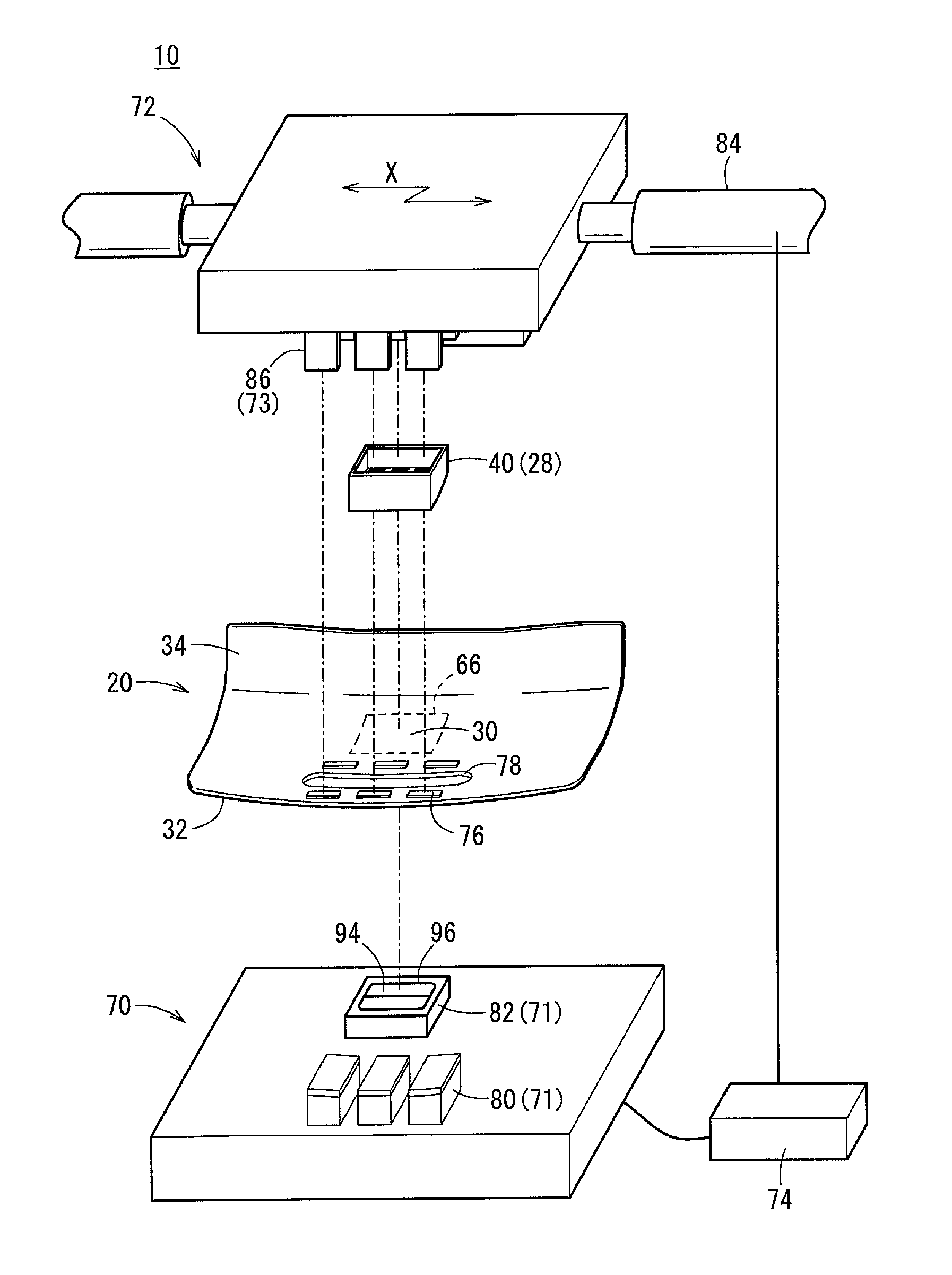
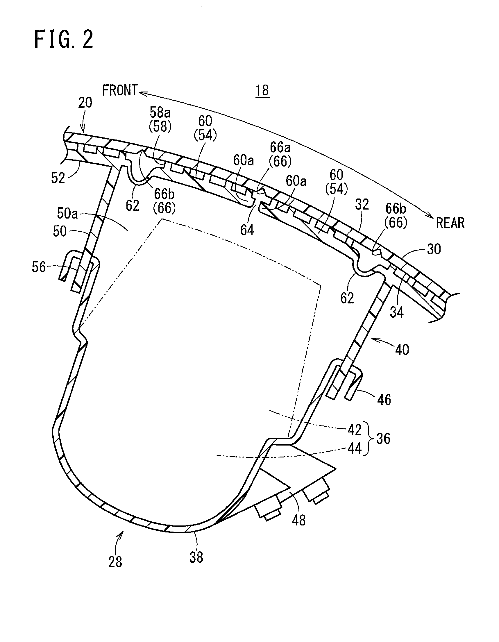
[0007]According to the above features, the vibration welding device, by means of a simple structure including the space disposed at a position overlapping with the cutout portion of the first workpiece, deformation of the first workpiece after vibration welding can be suppressed significantly. More specifically, although the first workpiece in the vicinity of the cutout portion is subjected to thermal expansion by heat produced at the time of vibration welding, and easily bulges or is raised in the thickness direction due to narrowing of the cutout portion, even if the first workpiece expands and bulges, such expansion and bulging can escape into the space that exists on the opposite side from the cutout portion. Owing thereto, accompanying cooling after vibration welding, the thermally expanded portion of the first workpiece that has moved into the space is suitably returned to its original location. Thus, after vibration welding, the first workpiece exhibits superior product quality without any (or almost no noticeable) depression in the vicinity where the cutout portion is formed.
[0009]In this manner, by fixing the first workpiece, during vibration welding, the vibration welding device is capable of allowing the thermally expanded portion on both sides in the vicinity of the cutout portion of the first workpiece to escape evenly into the space. Thus, after cooling upon completion of vibration welding, the thermally expanded portion in the vicinity of the cutout portion can return evenly, and a reduction in the occurrence of a depression can be further enhanced.
[0011]In this manner, by providing the position adjusting mechanism that enables a width or position of the space to be adjusted, the vibration welding device is capable of suitably adjusting the amount at which the first workpiece is displaced corresponding to the width of the space. Accordingly, after vibration welding, the condition of the first workpiece can easily be adjusted. Further, corresponding to the amount of heat, etc., at the time of vibration welding, or a change in the shape of the first or second workpiece (shape, material or thickness of the cutout portion, etc.), since the need to prepare a plurality of fixing parts is eliminated, versatility is increased.
[0017]According to the present invention, in the case that a workpiece having a cutout portion is subjected to vibration welding, by means of a simple structure, the product quality of the workpiece after vibration welding thereof can be enhanced.

Problems solved by technology

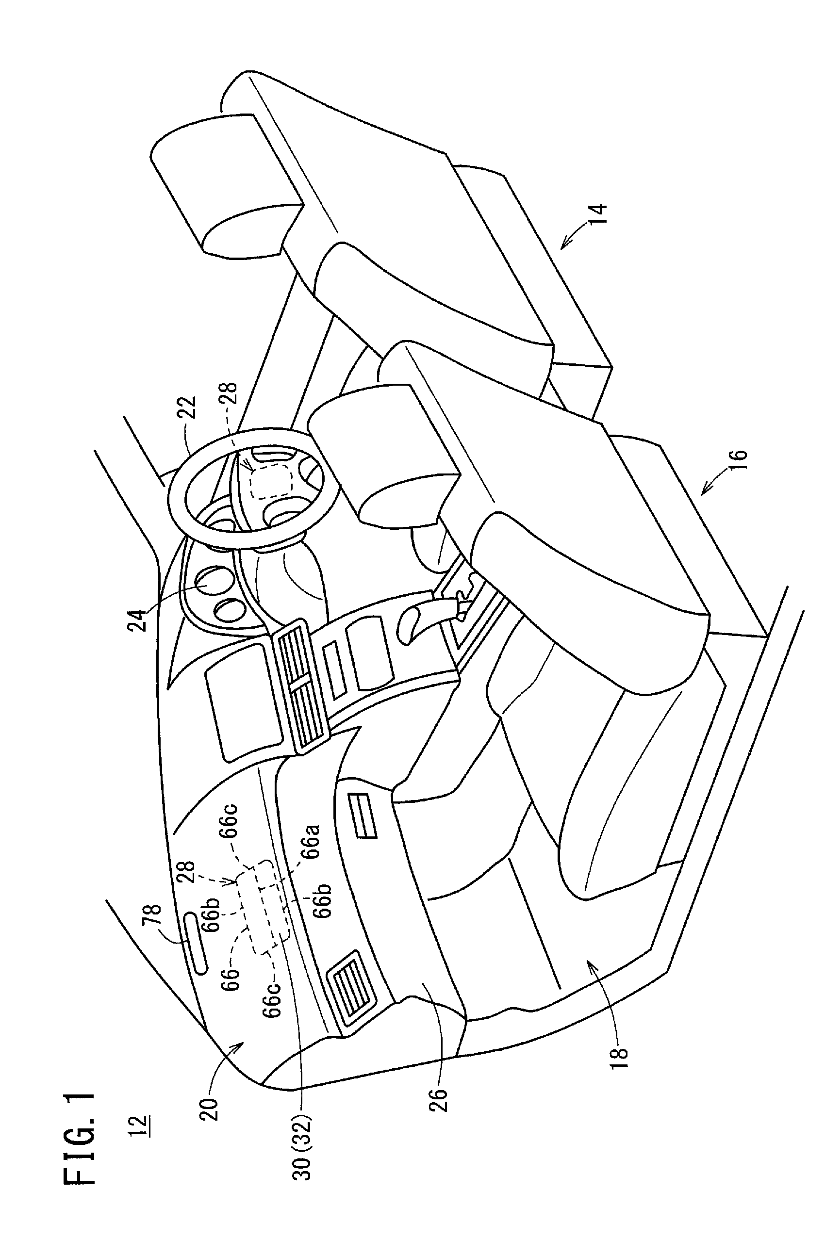
However, with an instrument panel equipped with a cutout portion, the location where the cutout portion is formed becomes deformed due to thermal effect on the instrument panel at the time of vibration welding, whereby after such vibration welding is carried out, a depression (deformation) tends to be produced along the cutout portion on a face (surface) opposite from the cutout portion.
When such a deformation is produced, the appearance of the instrument panel worsens and thus the quality in external appearance of the instrument panel is deteriorated.

Method used


Image

  • Vibration welding device and vibration welding method
  • Vibration welding device and vibration welding method
  • Vibration welding device and vibration welding method

Examples


first modification

[0090]A support jig 82A according to a first modification, as shown in FIGS. 9A through 9D, is equipped with a position adjusting mechanism 102 (position adjusting unit) capable of adjusting the width α and the position of a groove portion 100. The position adjusting mechanism 102 includes a plurality of divided sub-blocks 106 into which a support block 104 is divided, and block position fixing members 108 that enable the respective sub-blocks 106 to be moved relative to the base plate 70 and to be fixed in arbitrary positions.

[0091]The sub-blocks 106 include a function to individually narrow or widen first through third grooves 100a, 100b, 100c of the groove portion 100. In this case, a support block 104a that surrounds the groove portion 100 close to the frame member 90 is divided into four sub-blocks 106 corresponding to the adjacent second and third grooves 100b, 100c. On the other hand, two support blocks 104b that are surrounded by the second and third grooves 100b, 100c are e...

second modification

[0095]A support jig 82B according to a second modification, as shown in FIG. 10A, is of a configuration in which a width α′ of a groove portion 120 is set comparatively wide, and a depth β′ of the groove portion 120 is set shallowly. The depth β′ of the groove portion 120 is of a degree that enables a bottom wall 122 to contact the front surface 32 of the instrument panel 20 at the time of vibration welding. Consequently, even though the width α′ of the groove portion 120 is formed to be wide, when vibration welding is conducted, the amount of displacement of the front surface 32 of the instrument panel 20 is regulated by the bottom wall 122. As a result, accompanying cooling upon completion of vibration welding, the front surface 32 of the instrument panel 20 is able to return to a substantially flat shape.

third modification

[0096]With a support jig 82C according to a third modification, as shown in FIG. 10B, the edge of a groove portion 130 is formed with rounded corners 132. The groove portion 130 that is formed with such rounded corners 132 is capable of suppressing localized pressure on the front surface 32 of the instrument panel 20, when sandwiched between the support jig 82C and the vibration applying jig 88. Therefore, even though vibration welding is carried out, it is possible to reduce the possibility for marks or the like to be formed on the front surface 32 of the instrument panel 20.

[0097]Although a preferred embodiment of the present invention has been described above, the present invention is not limited to this embodiment, and it goes without saying that various modifications can be adopted within a scope that does not depart from the essential gist of the present invention. For example, the vibration welding device 10 is not limited to being applied to vibration welding of the instrume...


PUM

PropertyMeasurementUnit
thermal expansionaaaaaaaaaa
widthaaaaaaaaaa
thicknessaaaaaaaaaa

Abstract

This vibration welding device is a device that vibration welds an airbag holding box and an installment panel having a tear line. The vibration welding device is provided with a support jig that carries and affixes the installment panel during vibration welding. The support jig is provided with a groove that permits thermal expansion during vibration welding of the installment panel at a position differing from the tear line.

Description

TECHNICAL FIELD[0001]The present invention relates to a vibration welding device and a vibration welding method for vibration welding a plurality of workpieces.BACKGROUND ART[0002]Heretofore, in the case that workpieces made of resin or the like are joined together, vibration welding has been carried out in which a vibratory force is applied to the workpieces, whereby parts to be welded of the workpieces are heated and joined. In vibration welding, there is no need for adhesives, and further, after the welding process, there is no need for heat drying or the like. Thus, vibration welding is suitable for joining together interior members or components of an automobile.[0003]For example, in Japanese Laid-Open Patent Publication No. 2007-091024, a technique is disclosed in which an air bag chute is attached to an instrument panel of an automobile by vibration welding. In this case, so that the instrument panel can be broken smoothly when the airbag is deployed, a tear line, which is a ...

Claims


Application Information

Patent Timeline
Patent Type & Authority Applications(United States)
IPC IPC(8): B29C65/78B29C65/00B29C65/06
CPCB29C65/7841B29C65/0618B29L2031/3038B29C66/9516B29L2031/3008B29C66/9512B29C66/112B29C66/114B29C66/301B29C66/30223B29C66/532B29C66/534B29C66/542B29C66/81431B60R21/205B60R21/2165B29C66/9592B29C66/81435B29C66/61
Inventor MORIIZUMI, TAIKIKIKAWA, KEIICHISHINNO, YUSHI
Owner HONDA MOTOR CO LTD
Why Eureka
Try Eureka