Eureka AIR delivers breakthrough ideas for toughest innovation challenges, trusted by R&D personnel around the world.

Multi-wire sawing method and multi-wire sawing machine

A multi-wire cutting machine and multi-wire cutting technology are applied to fine working devices, manufacturing tools, stone processing equipment, etc., which can solve the problems of fewer workpieces, difficult operation, and affecting cutting accuracy, and achieve processing quality and Improved processing accuracy, wide application range, and improved workpiece quality

Active Publication Date: 2015-05-06
FUJIAN CHANGJIANG GOLDEN DRAGON RARE EARTH CO LTD
View PDF6 Cites 5 Cited by
  • Summary
  • Abstract
  • Description
  • Claims
  • Application Information

AI Technical Summary

Problems solved by technology

[0004] However, this kind of multi-wire cutting machine still has shortcomings, that is, its wire bow is still relatively large. If it is necessary to further reduce the wire bow, it is necessary to set more support rollers in the gap between the two workpieces, but due to the support The rollers rotate synchronously with the cutting line (that is, the support rollers have the same linear speed as the cutting line), therefore, in order to cut more workpieces, the diameter of the support rollers needs to be reduced as much as possible, however, the smaller the diameter of the support rollers , the faster the rotation speed, the greater the wear of the support roller; and increasing the diameter of the support roller, although the wear of the support roller can be reduced, but because it occupies too much volume, the corresponding length of the cutting line increases (that is, The length of the cutting line that cannot cut the workpiece is increased), resulting in a decrease in the number of workpieces that can be cut by the cutting line
[0005] In addition, the same as the line roller, the surface of the support roller must also be provided with annular grooves (the distance between the bottoms of two adjacent grooves is equal to the thickness of the workpiece). Therefore, if the cutting thickness of the work changes, the support roller The width of the groove also needs to be changed at the same time. Therefore, when changing the thickness of the cutting workpiece, it is necessary to replace the wire roller and the support roller at the same time, which is difficult to operate.
[0006] In addition, support rolls and line rolls are generally made of elastic wear-resistant materials (usually not rigid materials, because the wear of rigid material support rolls is severe, even if the surface is coated with zirconia wear-resistant layer, it will still produce huge wear) , to reduce loss. In addition, the support roller bearings are easy to wear after working for a long time at high speed and need to be replaced frequently. Broken wires, strained backup rolls and wire rolls

Method used


Image

  • Multi-wire sawing method and multi-wire sawing machine
  • Multi-wire sawing method and multi-wire sawing machine
  • Multi-wire sawing method and multi-wire sawing machine

Examples


Embodiment 1

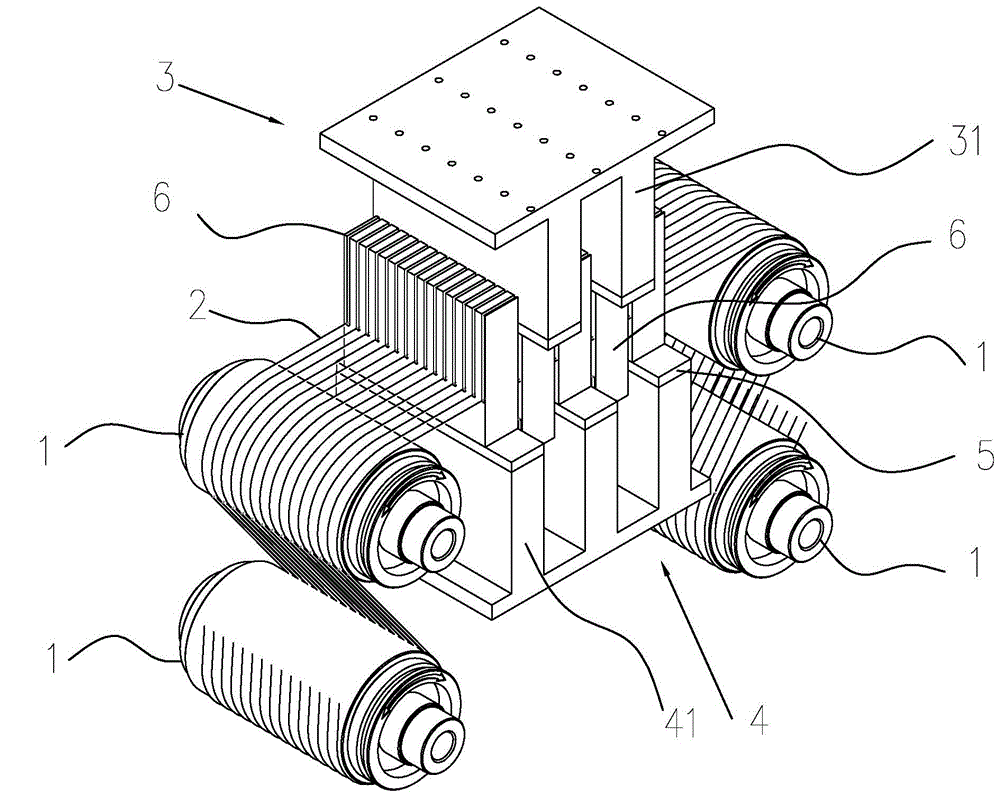
[0038] For specific embodiments of the present invention, refer to Figure 3 to Figure 6 , a multi-wire cutting machine, including four wire rollers (roller) 1, several cutting wires 2 arranged in parallel are wound on the wire rollers 1, and an upper workbench 3 and a lower workbench 4 are also included.

[0039]Wherein, the surface of each wire roller 1 is provided with an outer layer covered with polyurethane, and a plurality of grooves are arranged outside the polyurethane layer. And set the driving device (not shown) that the steel wire wound in the groove moves, and above-mentioned driving device is all prior art.

[0040] The upper workbench 3 is driven by a screw and a servo device, and can move in the up and down direction. Two parallel bosses 31 are formed below the upper workbench 3 and arranged at a certain distance. The bottom surface of each fixed column 31 is bonded with a Backing plate 5, in the present invention, the material of this backing plate is glass, a...


PUM


Abstract

The invention discloses a multi-wire sawing method and a multi-wire sawing machine. The multi-wire sawing method uses at least two parallel sawing wires wound on a wire roller, and at least two workpieces, wherein the workpieces are staggered at the upper and lower sides of the sawing wires, and respectively move to the directions of the sawing wires for sawing. The multi-wire sawing method uses a vertical compound sawing mode for eliminating wire arches; and the wire arched generated in sawing are shorter, so that the wire marks of the sawing wires left on the surfaces of the workpieces are reduced, and the workpiece quality is improved.

Description

technical field [0001] The invention relates to a mechanical processing method and a processing machine, in particular to a multi-wire cutting method and a multi-wire cutting machine. Background technique [0002] At present, multi-wire cutting machines are mostly used for cutting polycrystalline silicon ingots (rods) and monocrystalline silicon ingots (rods) of solar cells, as well as rare earth magnet blocks. Problems, especially when cutting rare earth magnets, due to the high hardness of the material to be cut, there is a problem that the wire bow is too large during the cutting process, and the wire bow is too large, in addition to affecting the cutting efficiency, it will also cause excessive vibration of the cutting line, And affect the surface quality and processing accuracy of the product. In addition, after each cutting program of the machine tool is completed, the worktable must be moved to eliminate the wire bow, and the cutting line is likely to break during thi...

Claims


Application Information

Patent Timeline
IPC IPC(8): B28D5/04
CPCB23H7/02B28D5/045
Inventor 刘华远永田浩王清江
Owner FUJIAN CHANGJIANG GOLDEN DRAGON RARE EARTH CO LTD
Why Eureka
Eureka Blog
Learn More