System, apparatus and method for providing cooling

a technology of cooling system and cooling device, applied in the field of machining, can solve the problems of reducing fatigue strength, limiting the thermal damage of workpieces, and reducing the fatigue strength of workpieces, and achieve the effect of improving the cooling

Active Publication Date: 2010-06-17
THE HONG KONG UNIV OF SCI & TECH
View PDF68 Cites 5 Cited by
  • Summary
  • Abstract
  • Description
  • Claims
  • Application Information

AI Technical Summary

Benefits of technology

[0019]Described herein is a system for providing cooling in a machining process or a system that generates heat. Unlike conventional systems that provide a limited cooling effect, various embodiments of this system can provide an adjustable cooling strength by generating mul...

Problems solved by technology

A major limiting factor in any machining process is thermal damage caused by heat.
The high temperature produced can cause various types of thermal damage to the workpiece, such as burning, phase transformation, softening of the surface layer with possible rehardening, unfavorable residual tensile stresses, cracks, and reduced fatigue strength.
To some extent, heat can also increase tool wear and reduce tool life.
In particular, it has been shown that water-based emulsions have better cooling effect, but generally lead to higher grinding forces.
Beyond machining processes, many mechanical or chemical systems also generate a significant amount of heat during their operations, due to frictions between components, combustions, or chemical reactions in the working zone.
However, for brittle materials, the very high temperature gradient may present a problem due to the possibilities in generating excessive thermal stresses on the surfaces of brittle materials.
In addition, th...

Method used


Image

  • System, apparatus and method for providing cooling
  • System, apparatus and method for providing cooling
  • System, apparatus and method for providing cooling

Examples


Embodiment Construction

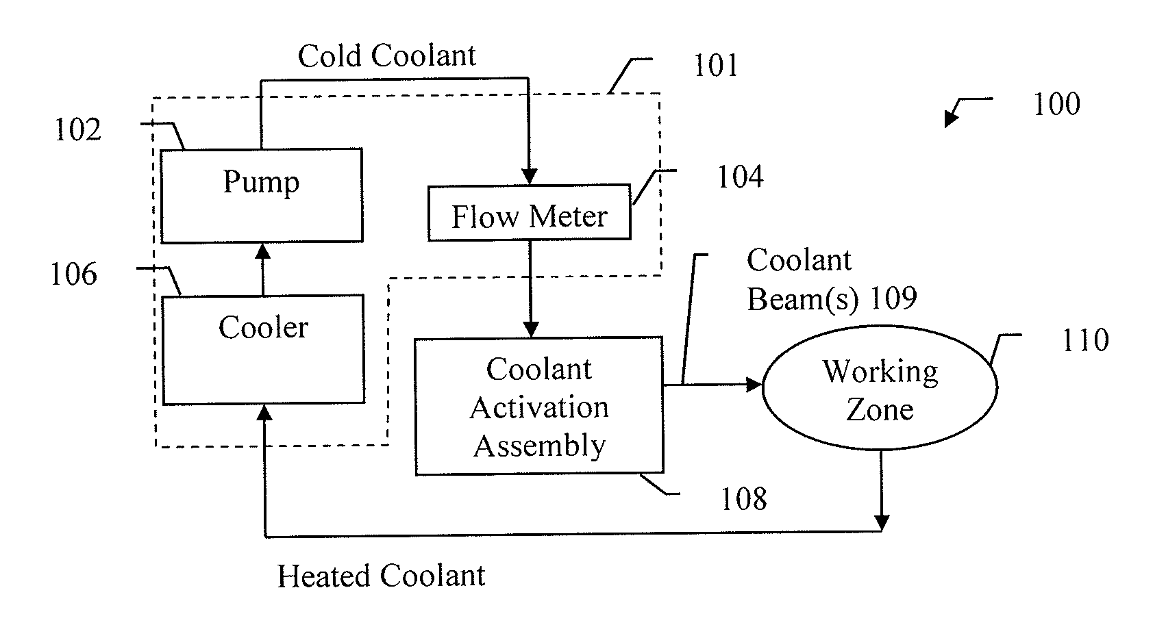
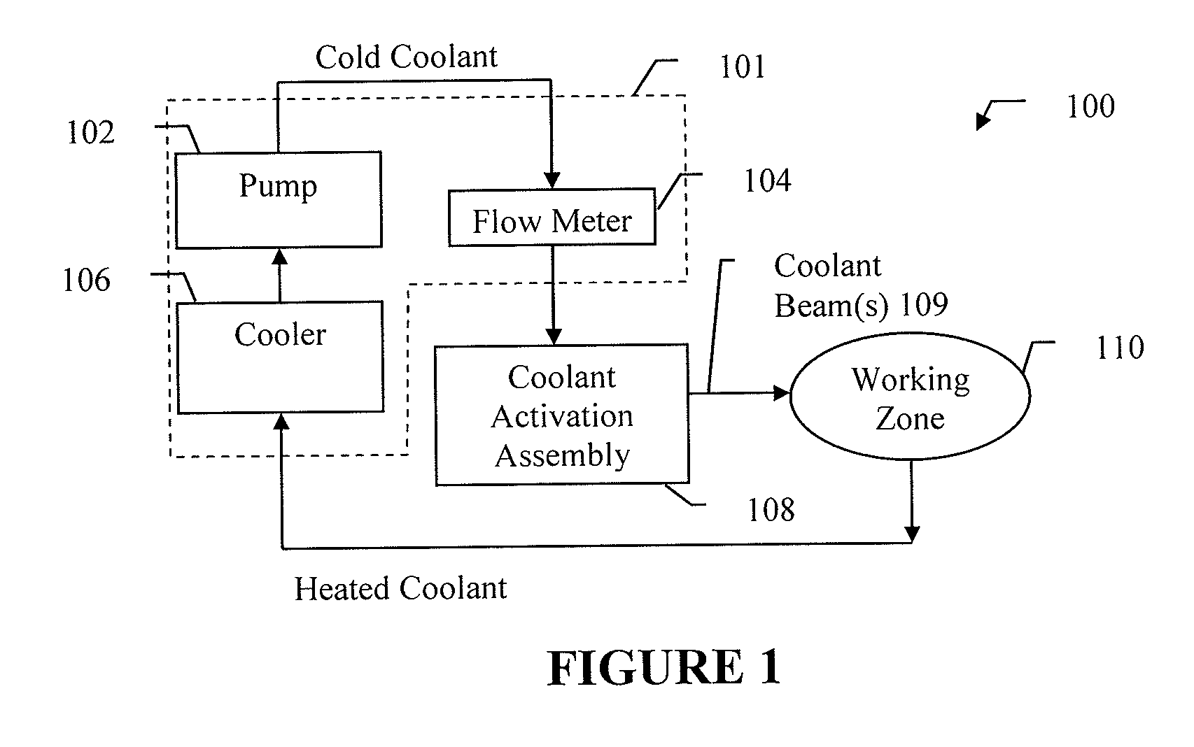
[0064]Now turning to the drawings, depicted in FIG. 1 is an embodiment of a system 100 for providing enhanced cooling in a machining process. As shown in the figure, system 100 includes a coolant supply 101 and a coolant activation assembly 108 that draws cold coolant from the coolant supply 101. The coolant activation assembly 108 generates a plurality of coolant beams 109, which is applied to a working zone 110 so that the heat generated within the working zone 110 is taken away by the coolant. The heated coolant, which absorbs and carries away the heat, is returned to the coolant supply 101, which cools and circulates the coolant back to the coolant activation assembly 108. As discussed above, the coolant can be gas or fluid as used in any existing cooling system.

[0065]The coolant supply 101 further includes a cooler 106 for cooling the heated coolant, a pump 102 for driving the coolant through the cooler 106 to form a coolant flow and deliver the cold coolant flow to the coolant...


PUM

PropertyMeasurementUnit
Fractionaaaaaaaaaa
Temperatureaaaaaaaaaa

Abstract

Described herein is a system for generating a plurality of coolant beams that converge at a focal point for advanced heat transfer. The system utilizes a variable strength activation of coolant and superposition of coolant beams generated by multiple actuators for increased cooling strength increase, thereby avoiding activation saturation in conventional systems. Each coolant beams is activated to carry an ultrasonic or megasonic vibration component. In addition, the system includes a coolant activation assembly having a plurality of actuators for generating the coolant beams. The coolant activation assembly further includes supporting components for positioning the actuators so that all of the coolant beams generated by these actuators converge at the focal point. Experimental results show that the system provides significantly improved workpiece quality in a machining process. Compared with the most advanced existing system, this system offers a further improvement of up to 12.30% on surface roughness of the finished workpiece.

Description

CROSS-REFERENCE TO RELATED APPLICATIONS[0001]This patent application claims the benefit of U.S. Provisional Patent Application No. 60 / 193,564, filed Dec. 8, 2008, which is incorporated by reference in its entirety.TECHNICAL FIELD[0002]This invention is related in general to the field of machining and in particular to a system for providing cooling in a machining or chemical process that requires cooling.BACKGROUND OF THE INVENTION[0003]As the most important manufacturing process in modern industry, machining is defined as the process of removing material from a workpiece in the form of chips. To perform the machining operation, relative motion is introduced between the tool and the workpiece. This relative motion is achieved in most machining operations by means of a primary motion, called cutting speed and a secondary motion, called feed. The shape of the tool and its penetration into the workpiece surface, combined with these motions, produce the desired shape of the resulting wor...

Claims


Application Information

Patent Timeline
IPC IPC(8): B23Q11/10B23Q11/12F25B1/00
CPCB23Q11/10Y10T409/304032Y10T408/46B23Q11/1046B23Q11/1084Y02P70/10
Inventor GAO, YONGSHENGZHOU, SHENGYIN
Owner THE HONG KONG UNIV OF SCI & TECH
Why Eureka
Try Eureka