
Method and apparatus for limiting in-rush current to a starter motor of a vehicle

a technology for starter motors and motor vehicles, which is applied in the direction of engine starters, electric motor starters, combustion engines, etc., can solve the problems of unsatisfactory voltage drop and the slow start-up performance of motor vehicles, and achieve high in-rush current, high torque, and significant voltage drop

Active Publication Date: 2012-05-17
FORD GLOBAL TECH LLC
View PDF6 Cites 9 Cited by
  • Summary
  • Abstract
  • Description
  • Claims
  • Application Information

AI Technical Summary

Benefits of technology

[0008]By applying different levels of in-rush current to a starter motor that engages an engine during engine starting, it may be possible to provide a vehicle system voltage that allows for continued operation of other vehicle electrical power consumers during engine cranking. For example, in-rush current supplied to a starter motor during engine cranking can be reduced when a vehicle speed is above a threshold level to allow electrically assisted brakes to operate. In this way, operation of vehicle electrical power consumers can continue even during engine cranking.
[0009]The present description may provide several advantages. Specifically, the approach may allow additional vehicle electrical consumers to operate during engine cranking. Further, the approach can provide different levels of in-rush current for different vehicle speeds so that when the engine is started via a starter and vehicle kinetic energy (e.g., rotating the engine via vehicle wheel torque) a desirable level of starter current is provided. Further still, the approach provides for a higher level of starter current during cold engine starting.
[0011]It should be understood that the summary above is provided to introduce in simplified form a selection of concepts that are further described in the detailed description. It is not meant to identify key or essential features of the claimed subject matter, the scope of which is defined uniquely by the claims that follow the detailed description. Furthermore, the claimed subject matter is not limited to implementations that solve any disadvantages noted above or in any part of this disclosure.

Problems solved by technology

However, if the motor vehicle is operated in an automatic stop-start mode when the vehicle is moving in a so called ‘dynamic’ stop-start mode then the relatively high in-rush current normally used for a ‘static’ start may result in an undesirable voltage drop.
However, if a lower level of in-rush current is continuously set so as to prevent an undesirable voltage drop for ‘dynamic’ automatic restarts, then the start-up performance of the motor vehicle may be slower than is desired for ‘static’ automatic restarts.

Method used


Image

  • Method and apparatus for limiting in-rush current to a starter motor of a vehicle
  • Method and apparatus for limiting in-rush current to a starter motor of a vehicle
  • Method and apparatus for limiting in-rush current to a starter motor of a vehicle

Examples


Embodiment Construction

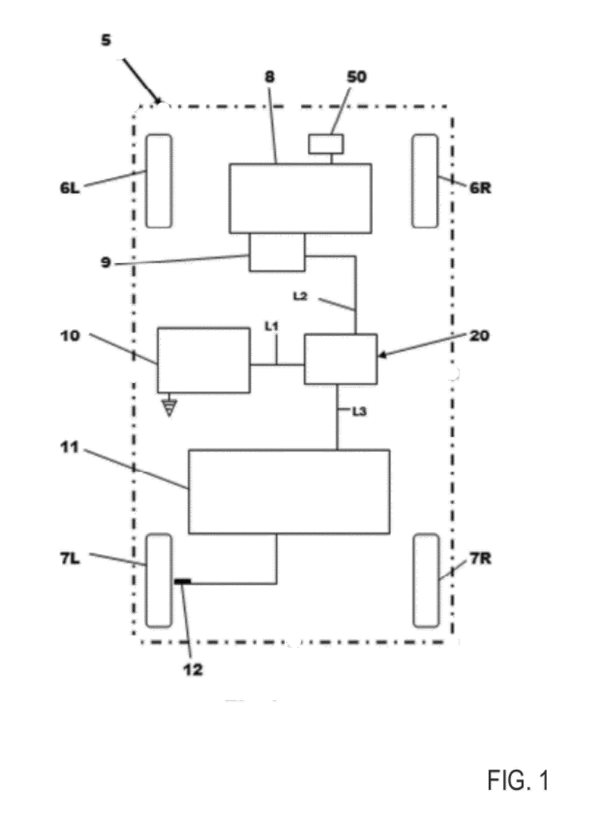
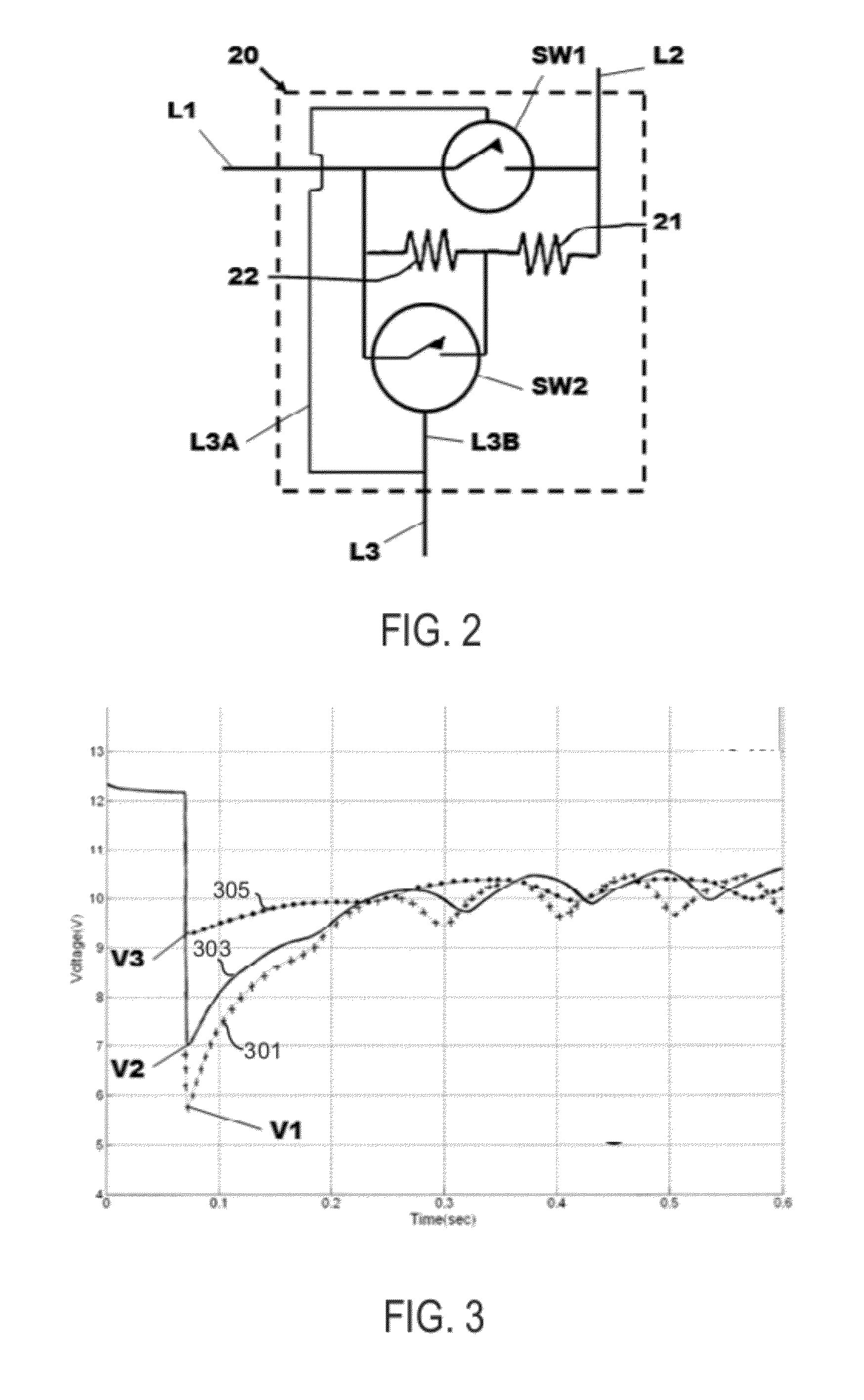
[0019]The present description is related to starting an engine of a stop / start vehicle. In one example, the system applies to a vehicle as shown in FIG. 1. The system may be implemented with current in-rush circuits as shown in FIGS. 2 and 5. The system can vary vehicle system voltage as illustrated in FIG. 3. The system may include a method executable via instructions of a controller as shown in FIG. 4.

[0020]According to a first aspect of the description there is provided a method of limiting the in-rush current to a starter motor of an engine of a motor vehicle comprising providing at least two levels of in-rush current restriction and applying a level of in-rush current restriction to the starter motor based upon the current operating speed of the motor vehicle. There may be a first level of in-rush current restriction and a second level of in-rush current restriction that is higher than the first level of in-rush current restriction. In one example, the first level of in-rush cu...


PUM


Abstract

A system and method for limiting engine starting current of a starter motor of an engine is described. In one example, starter motor current is controlled according to vehicle speed. The method may allow vehicle system voltage to remain at a higher level during automatically initiated engine starts.

Description

RELATED APPLICATIONS[0001]This application claims priority to United Kingdom Patent Application No. 1019079.1, filed Nov. 11, 2010, entitled “A Method and Apparatus for Limiting the In-Rush Current to a Starter Motor of a Motor Vehicle,” the entire contents of which are herein incorporated by reference for all purposes.FIELD[0002]The present description relates to motor vehicles and in particular to a motor vehicle having an engine and an automatic stop-start system for the engine.BACKGROUND AND SUMMARY[0003]It may be desirable to control the in-rush current to a starter motor for an engine of a motor vehicle by providing a resistance arranged in series with the starter motor. For a conventional or ‘static’ stop-start system, the vehicle is stationary when the engine is stopped and started and so a significant voltage drop due to a relatively high in-rush current is permissible since a relatively high amount of torque may be used to start the vehicle. It is desirable to permit a rel...

Claims


Application Information

Patent Timeline
Patent Type & Authority Applications(United States)
IPC IPC(8): F02N11/08
CPCF02N11/0814F02N11/087F02N2250/02Y02T10/48F02N2200/0801Y02T10/40F02N11/08
Inventor CONNELLY, CHRISCONEN, MARK
Owner FORD GLOBAL TECH LLC
Learn More