Self-adaptive current-mode-control circuit for a switching regulator

a switching regulator and current mode control technology, applied in the field of system and method of controlling power electronic circuitry, can solve the problems of increasing complexity, affecting the operation of the switching regulator, so as to achieve the effect of reducing the complexity of the switching regulator

Active Publication Date: 2012-05-17
INTEGRATED DEVICE TECH INC
View PDF7 Cites 63 Cited by
  • Summary
  • Abstract
  • Description
  • Claims
  • Application Information

AI Technical Summary

Benefits of technology

[0006]In accordance with some embodiments, a current-mode-control circuit for a switching regulator is provided. The circuit includes a first transistor coupled to a power supply voltage and to a first node, a second transistor coupled to the first node, an inductor coupled between the first node and an output of the current mode control circuit, and a slope compensation generation circuit coupled to the output of the current control circuit through a feedback loop. The slope compensation generation circuit generates a slope compensation current related to the output voltage, and the circuit further includes an inductor current sensing circuit coupled to the first transistor and the second transistor, and configured to calculate a current through the inductor and output a inductor sense current, and a pulse-width modulation control circuit coupled to the slope generation circuit and the inductor cu...

Problems solved by technology

However, despite the given advantages over linear regulators, switching regulators commonly have disadvantages such as greater complexity, the generation of high-amplitude and high-frequency energy, and ripple voltage noises at the switching frequency and its harmonic frequencies.
Because of the harmonic noises and the high-amplitu...

Method used


Image

  • Self-adaptive current-mode-control circuit for a switching regulator
  • Self-adaptive current-mode-control circuit for a switching regulator
  • Self-adaptive current-mode-control circuit for a switching regulator

Examples


Embodiment Construction

[0019]In the following description, specific details are set forth describing embodiments of the present disclosure. It will be apparent, however, to one skilled in the art that some embodiments may be practiced without some or all of these specific details. The specific embodiments disclosed herein are meant to be illustrative but not limiting. One skilled in the art may realize other material that, although not specifically described here, is within the scope and the spirit of this disclosure.

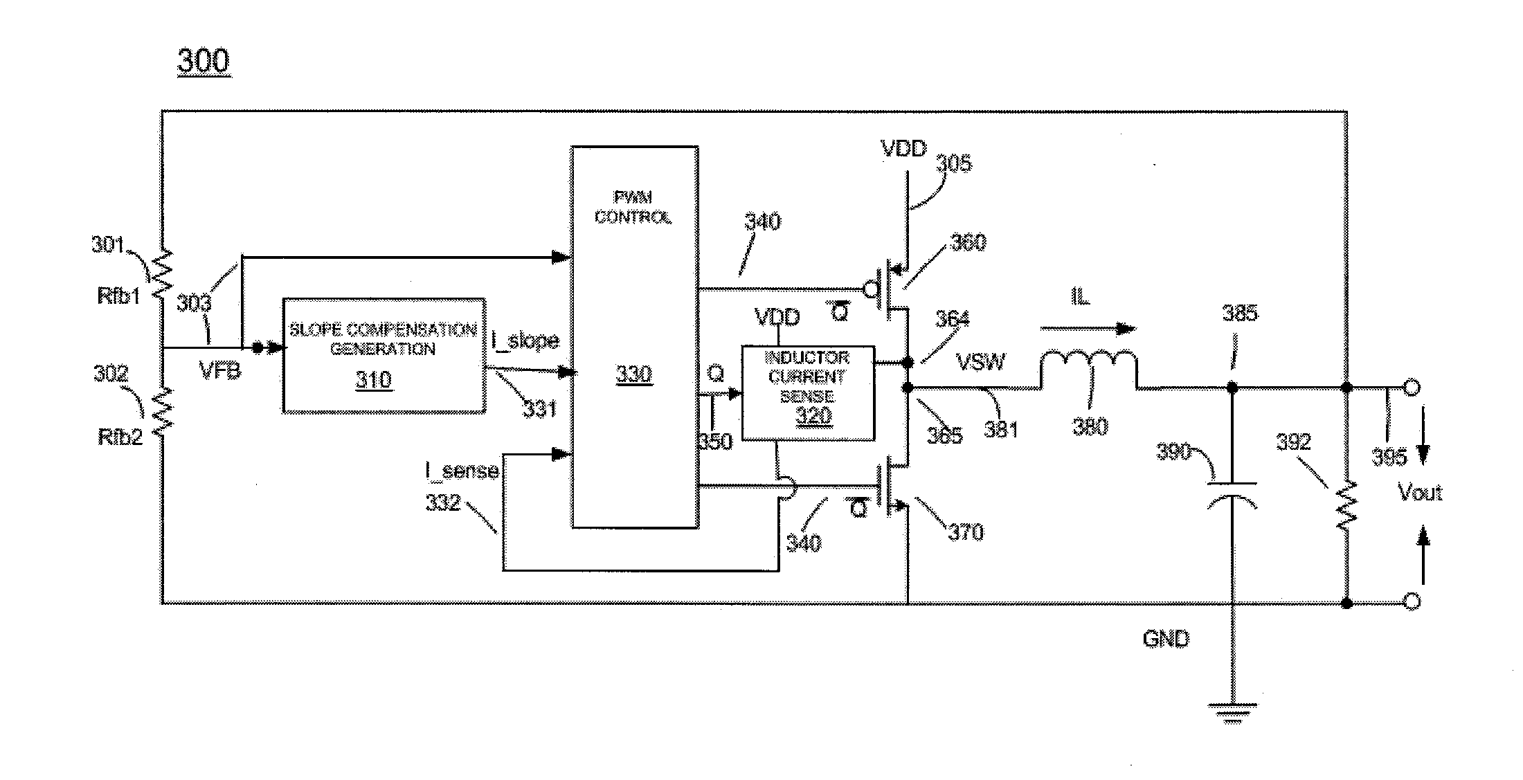
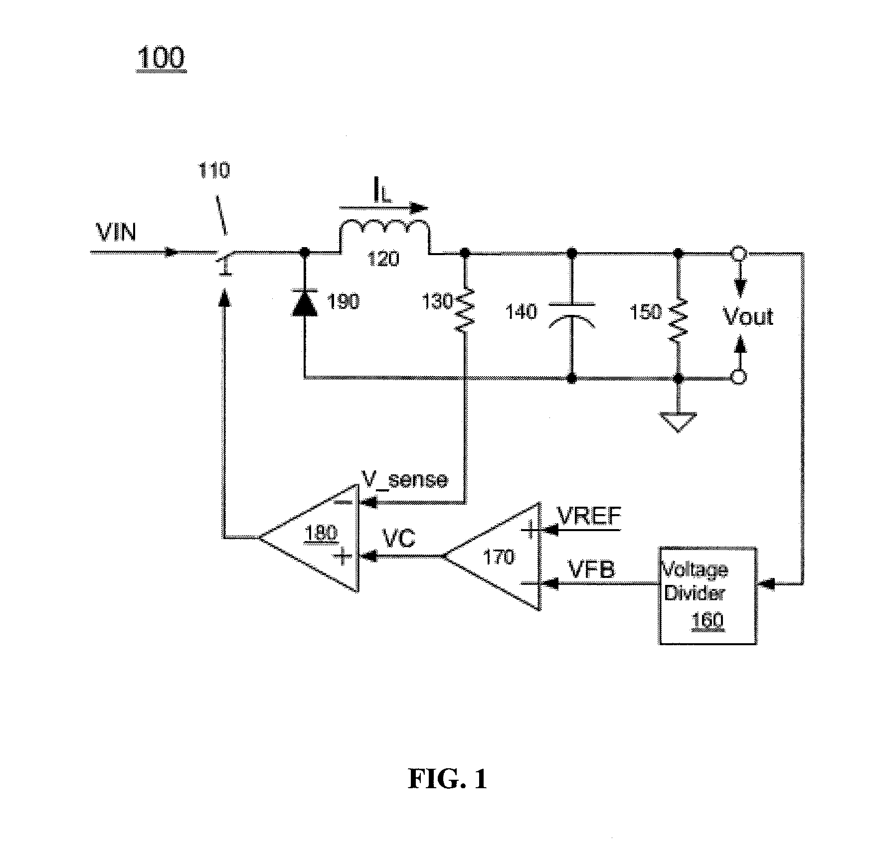
[0020]Switching regulators typically have two control modes: a voltage-control mode and a current-control mode. The voltage-control mode often requires an LC filter that adds conjugate poles, resulting in a difficult control loop design and a slower transient response. However, the current-control mode uses an extra current control loop alongside a voltage control loop. This current control loop senses the inductor current and changes the two conjugate poles into one pole in a low frequency f...


PUM


Abstract

A current-mode-control circuit for a switching regulator is provided. The circuit includes a first transistor coupled to a power supply voltage, a second transistor, and an inductor. The circuit further includes a slope compensation generation circuit coupled to the output of the current control circuit through a feedback loop, the slope compensation generation circuit generating a slope compensation current related to the output voltage, an inductor current sensing circuit coupled to the first transistor and the second transistor, and configured to calculate a current through the inductor and output a inductor sense current, and a pulse-width modulation control circuit coupled to the slope generation circuit and the inductor current sense circuit, the pulse-width modulation control circuit receiving the output of the current control circuit, the slope compensation current and the inductor sense current as inputs.

Description

TECHNICAL FIELD[0001]The present disclosure relates to a system and a method of controlling power electronic circuitry, in particular, to an active switching voltage regulator in power supplies.DISCUSSION OF RELATED ART[0002]Voltage regulators are used to automatically maintain a constant voltage level. Most active modern electronic voltage regulators typically operate by comparing the actual output voltage to some internal fixed reference voltage. Any difference between the actual output voltage and the internal fixed reference voltage is amplified and used to control a regulation element in such a way as to reduce the difference. Typical regulators include active regulators such as linear, switching, silicon controlled rectifier (SCR) regulators, electromechanical regulators, and coil-rotation AC voltage regulators.[0003]Active regulators, including linear and switching regulators, are named as such because they use at least one active component such as a transistor or operational...

Claims


Application Information

Patent Timeline
IPC IPC(8): G05F1/00
CPCH02M3/1588Y02B70/1466H02M2001/0025H02M2001/0009G05F1/10H02M3/156H02M1/0009H02M1/0025Y02B70/10
Inventor SONG, ANFEI
Owner INTEGRATED DEVICE TECH INC
Why Eureka
Try Eureka