Testing Auxiliary Apparatus

a technology of auxiliary equipment and test tubes, which is applied in the direction of measurement devices, printed circuit testing, instruments, etc., can solve the problems of repeated soldering operations, damaged surrounding components, and difficult alignment of probes with component pins, so as to avoid wrong contacts and short circuits, save testing time, and improve testing efficiency

Inactive Publication Date: 2012-05-17
ASKEY COMP
View PDF26 Cites 13 Cited by
  • Summary
  • Abstract
  • Description
  • Claims
  • Application Information

AI Technical Summary

Benefits of technology

[0012]According to the present invention, since the extension testing points are disposed on the testing platform and electrically connected to the probes on the testing platform, the tester only needs to bring a probe head of the testing apparatus into contact with the extension testing points for signal testing of the circuit board, thereby avoiding the inconvenience of searching for tiny testing points on the circuit board with high-density pins so as to effectively avoid wrong contacts and short circuits, save the testing time and improve the testing efficiency.

Problems solved by technology

However in practice, limited by surrounding components, the testing probes are not easy to be aligned with the component pins, and even a short circuit may occur to pins of a surrounding component (such as ground terminals of a capacitor) to thereby damage the surrounding component.
However, during such a process, the signal connection points may be accidentally knocked off the circuit board and accordingly the soldering operation needs to be repeated.
Therefore, the above-described testing process requires soldering operations or repeated manual connecting / disconnecting operations, which is labor and time-consuming and results in a low testing efficiency.
Further, if the testing points are tiny or densely distributed, the testing probes are difficult to be manually aligned and brought into contact with the testing points such that the testing probes may be in contact with wrong testing points.
Even worse, the testing probes may be in contact with pins of a neighboring component so as to result in a short circuit and damage the circuit board, thereby increasing the testing cost.

Method used


Image

  • Testing Auxiliary Apparatus
  • Testing Auxiliary Apparatus
  • Testing Auxiliary Apparatus

Examples


Embodiment Construction

[0016]The following embodiments are provided to illustrate the present invention. Those skilled in the art will readily understand other advantages and functions of the present invention in accordance with the contents disclosed in this specification. The present invention can also be performed or applied by other different embodiments. Various modifications and variations based on different viewpoints and applications can be made in the details of the specification without departing from the spirit of the present invention.

[0017]It should be noted that the drawings are simplified schematic diagrams and only show components relating to the present invention. In practice, the layout of the components may be far more intricate.

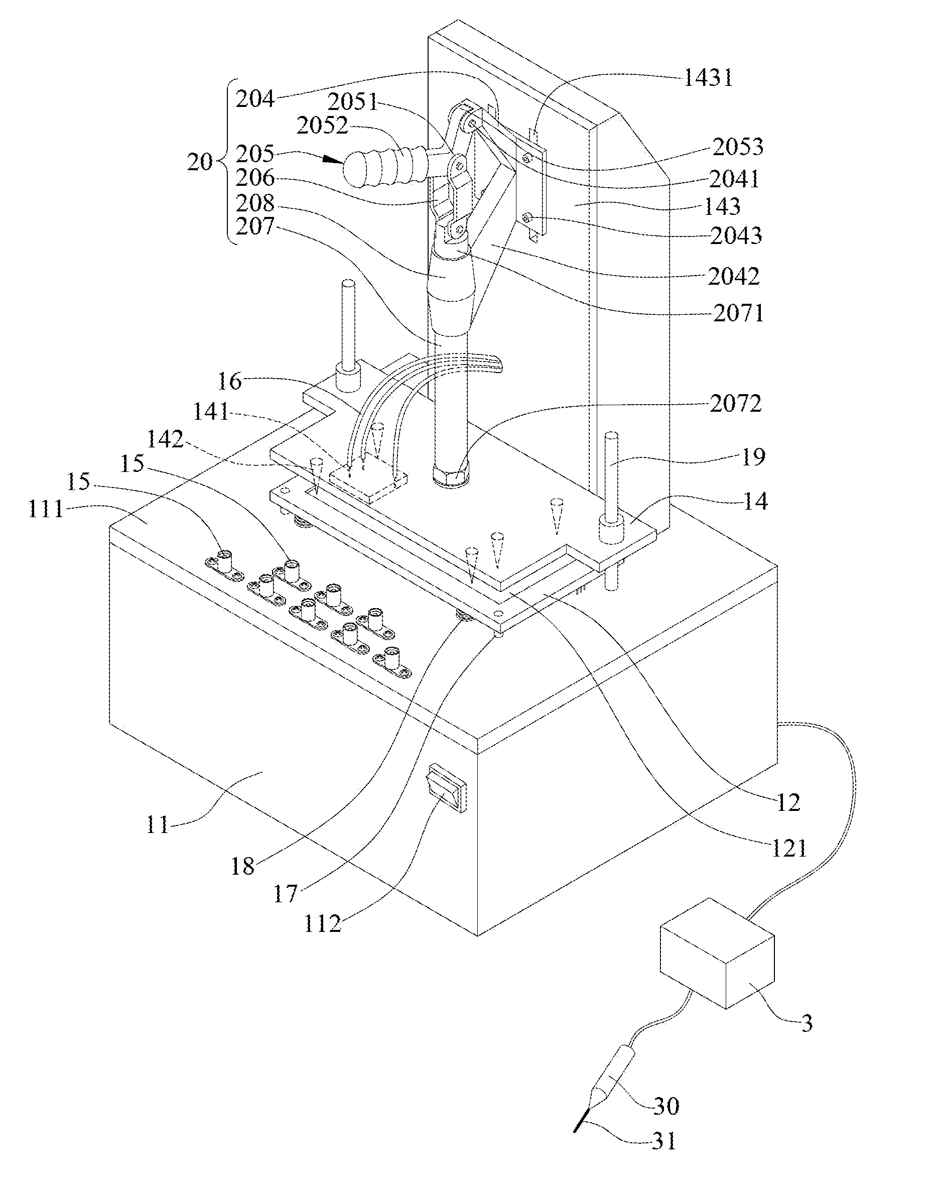
[0018]FIG. 1 is a perspective view of a testing auxiliary apparatus according to the present invention. Referring to the drawing, the testing auxiliary apparatus is used for assisting a testing apparatus 3 to capture and test voltage or frequency signals of a pl...


PUM


Abstract

A testing auxiliary apparatus for assisting a testing apparatus to test signals of testing points of a circuit board, includes: a testing base having a testing platform with probes vertically disposed thereon and corresponding to the testing points, and extension testing points exposed from the testing platform and electrically connected to the probes so as for the testing apparatus to test signals; a carrier board disposed on the testing base and capable of ascending and descending relative to the testing platform and including a positioning portion for positioning the circuit board and through holes corresponding to the probes; and a pressing member disposed on the testing base for pressing the circuit board and driving the carrier board to descend such that the probes come into contact with the testing points through the through holes, thereby avoiding the inconvenience of searching for testing points on the circuit board with high-density pins.

Description

BACKGROUND OF THE INVENTION[0001]1. Field of the Invention[0002]The present invention relates to testing apparatus, and more particularly, to a testing auxiliary apparatus for capturing signals of a plurality of testing points of a circuit board under test through a plurality of probes.[0003]2. Description of Related Art[0004]Generally, before an electronic product such as a computer, a network device or a household appliance is mass produced or delivered, the circuit board thereof is tested to ascertain whether it functions properly, thereby ensuring a good quality of the product.[0005]A common testing process for a circuit board involves introducing signals to a testing apparatus (such as a voltage testing apparatus, a frequency counter or an oscilloscope) so as to capture the frequency or waveform of signals of testing points on the circuit board. Therefore, testing probes are required to capture signals from selected testing points. The testing points can be component pins on th...

Claims


Application Information

Patent Timeline
Patent Type & Authority Applications(United States)
IPC IPC(8): G01R1/067G01R31/00
CPCG01R31/2808
Inventor YU, ZHONG-YUANHSIEH, CHING-FENG
Owner ASKEY COMP
Why Eureka
Try Eureka