Lighting device, display device and television receiver

a technology of display device and light fixture, which is applied in the direction of lighting support device, television system, instruments, etc., can solve the problems of workability tending to degrade, poor workability in the screw attachment and detach operation itself, and easy releas

Inactive Publication Date: 2012-05-17
SHARP KK
View PDF2 Cites 11 Cited by
  • Summary
  • Abstract
  • Description
  • Claims
  • Application Information

AI Technical Summary

Benefits of technology

[0009]With this configuration, to attach the light source board to the chassis, in the state where the light source board is stored in the chassis, the attachment portion of the board holding member is inserted into the attachment hole of the chassis, and the board holding member located at the non-holding position is rotated along the plate surface of the chassis. Then, the board holding member reaches the holding position, and the attachment portion overlaps with the edge of the attachment hole in a plan view and sandwiches the edge of the attachment hole between the attachment portion and the body portion, resulting that the board holding member is held to be attached to the chassis. In this state, the light source board is sandwiched between the body portion of the board holding member and the chassis, thereby being held to be attached to the chassis. Conversely, to detach the light source board from the chassis, the board holding member located at the holding position is rotated such that the attachment portion is located at the non-holding position at which the attachment portion does not overlap with the edge of the attachment hole in a plan view. At the non-holding position, since detaching of the attachment portion from the attachment hole is allowed, the board holding member can be detached from the chassis. As a result, since the holding state of the light source board by the board holding member is released, the light source board can be detached from the chassis.
[0010]Conventionally, since the light source board is screwed, the workability in the screw attaching and detaching operation itself is poor and therefore, workability tends to degrade. However, according to the present invention, by rotating the board holding member along the plate surface of the chassis between the non-holding position and the holding position, the board holding member can easily hold the light source board and the holding state can easily be released. Thus, the workability in attaching and detaching the light source board is excellent.
[0011]Since the board holding member according to the present invention holds the light source board between the board holding member and the chassis, for example, when the light source mounted on the light source board has a failure and replacement or repair of the light source board is required, it is needed to detach each of the board holding member and the light source board from the chassis. On the contrary, in the case of a lamp clip holding a cold-cathode tube, only the detaching operation of the cold-cathode tube is required. As compared to the case of the lamp clip, the frequency of the detaching operation of the board holding member tends to be higher. Furthermore, since the number of light source boards used tends to increase with an increase in the lighting device in size, the number of light source boards used and the number of times of the attaching and detaching operation of the board holding member tend to increase. In consideration of such circumstances, by improving the workability in attaching and detaching the board holding member holding the light source board, the workability in repairing the lighting device as well as the workability in the case of upsizing of the lighting device can be remarkably improved.

Problems solved by technology

Conventionally, since the light source board is screwed, the workability in the screw attaching and detaching operation itself is poor and therefore, workability tends to degrade.

Method used


Image

  • Lighting device, display device and television receiver
  • Lighting device, display device and television receiver
  • Lighting device, display device and television receiver

Examples


first embodiment

[0099]A first embodiment of the present invention will be described with reference to FIGS. 1 to 21. In this embodiment, a liquid crystal display device 10 is used as an example. A part of each figure shows an X-axis, a Y-axis and a Z-axis, and a direction of each axis is represented in each figure. It is given that an upper side in FIGS. 4 and 5 is a front side and a lower side in these figures is a back side.

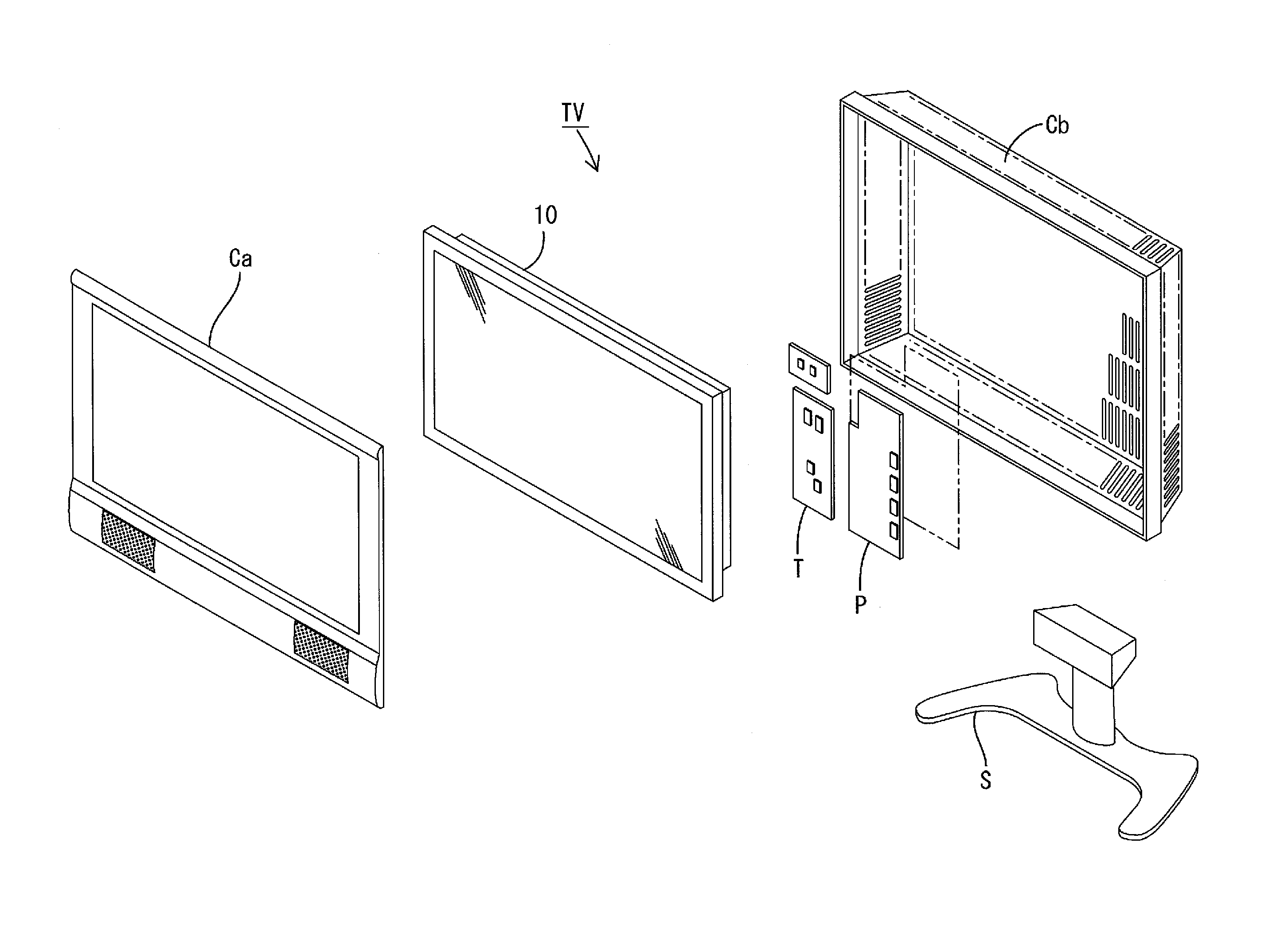
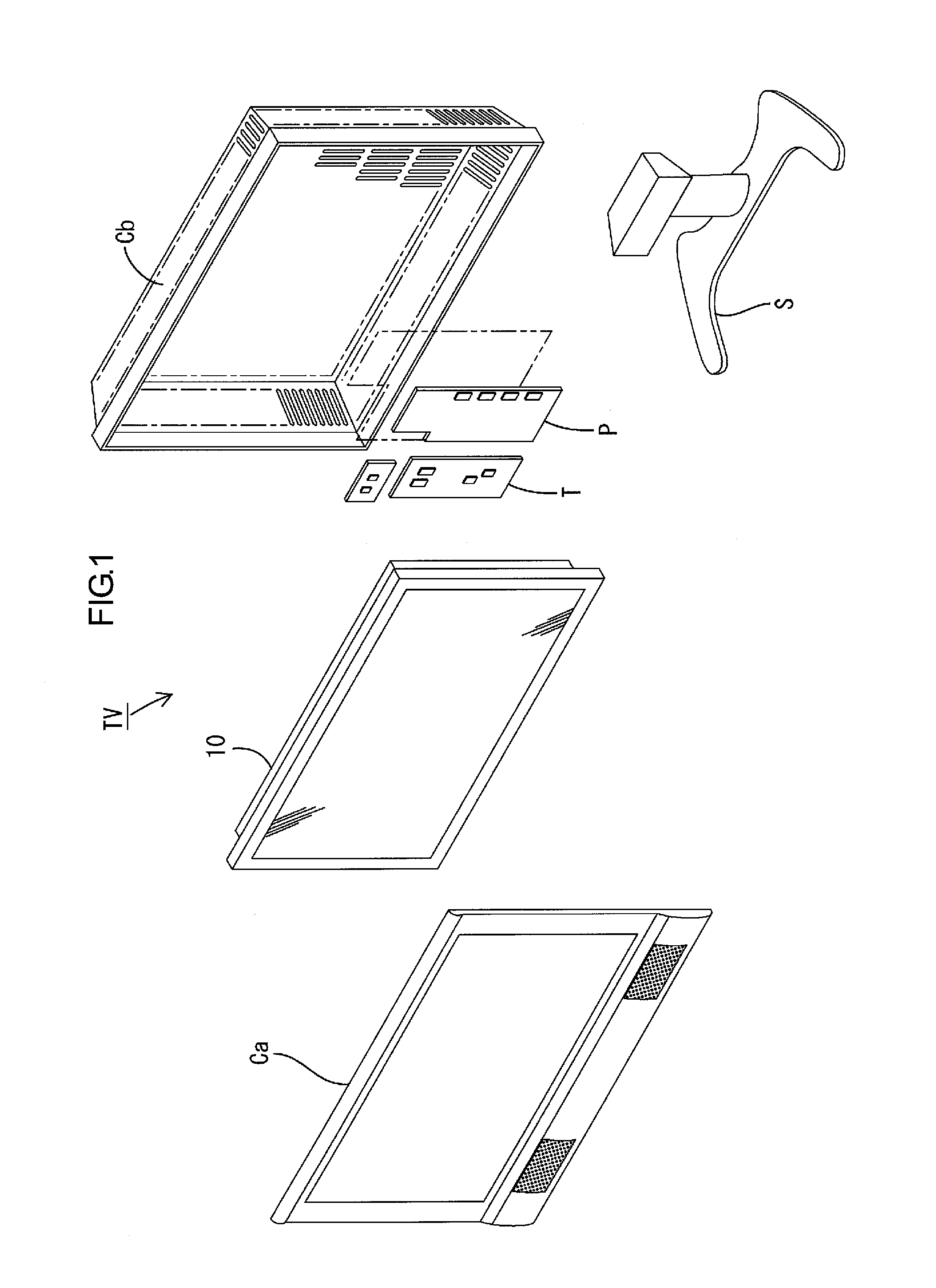
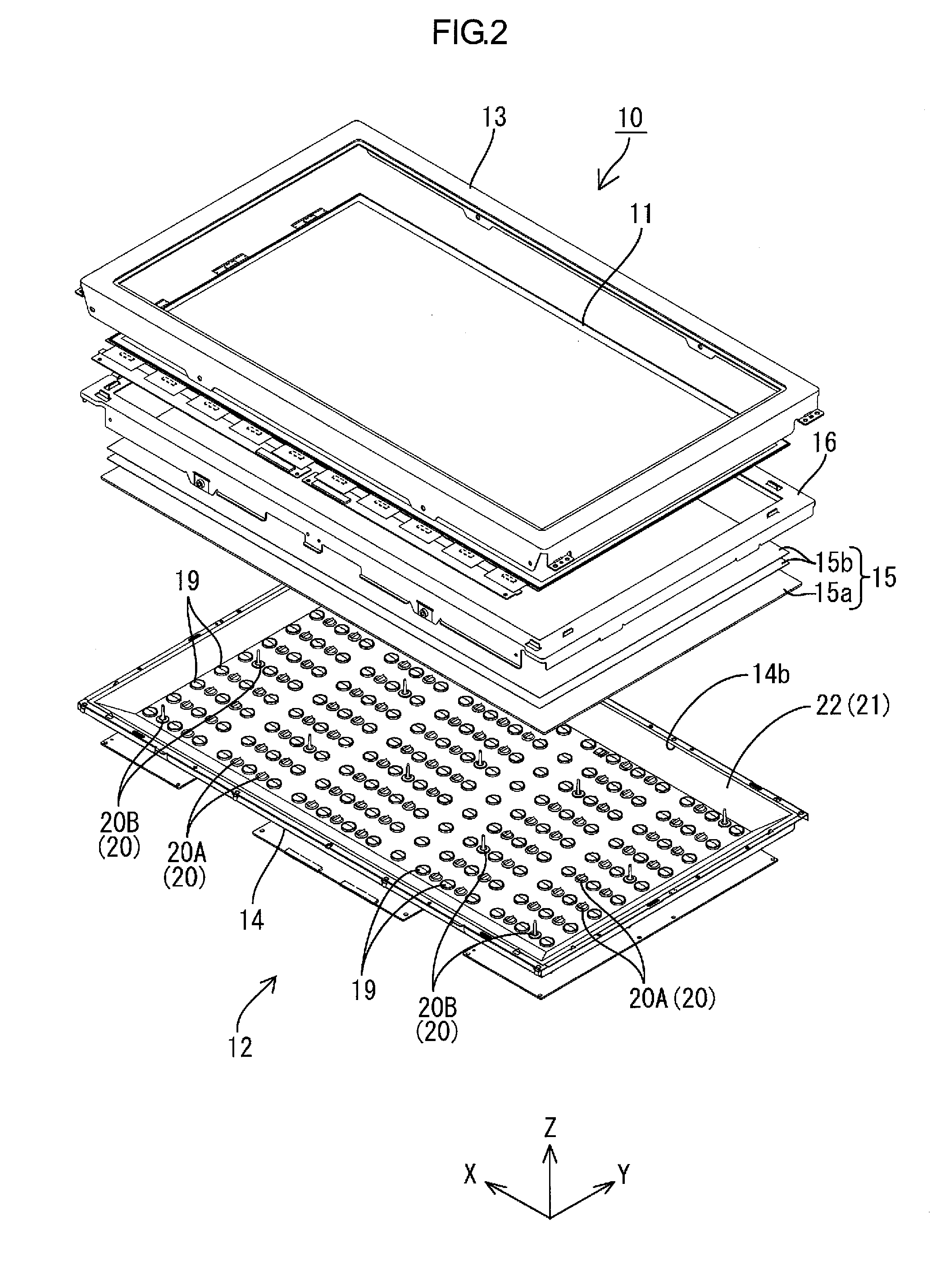
[0100]A television receiver TV according to this embodiment includes, as shown in FIG. 1, the liquid crystal display device 10, front and back cabinets Ca and Cb that store the liquid crystal display device 10 therebetween, a power source P, a tuner T and a stand S. The liquid crystal display device (display device) 10 is shaped like an oblong quadrangle as a whole (rectangular) and is stored in a vertically mounted state. The liquid crystal display device 10 includes, as shown in FIG. 2, a liquid crystal panel 11 as a display panel and a backlight unit (lighting device) 12 as...

first modification example of first embodiment

[0190]A first modification example of the first embodiment will be described with reference to FIG. 24. Here, a gripping portion 27-1 of modified shape is shown.

[0191]As shown in FIG. 24, the gripping portion 27-1 has a trapezoidal cross section cut along its short-side direction. With this configuration, the thickness of the gripping portion 27-1 is larger than that of the gripping portion 27 in the first embodiment and thus, the strength is excellent.

second modification example of first embodiment

[0192]A second modification example of the first embodiment will be described with reference to FIG. 25. Here, a gripping portion 27-2 of modified shape is shown.

[0193]As shown in FIG. 25, the gripping portion 27-2 is substantially block-like as a whole, and its protruding front end is circular arcuate. That is, the width (dimension in the short-side direction) of the gripping portion 27-2 is uniform except for the protruding front end. Accordingly, the strength of the gripping portion 27-2 is more excellent than the gripping portion 27 described in the first embodiment, the width of which is continuously decreased.


PUM

PropertyMeasurementUnit
rotational angleaaaaaaaaaa
sizeaaaaaaaaaa
sizeaaaaaaaaaa

Abstract

A backlight unit 12 according to the present invention includes LEDs 17 as light sources, an LED board 18 mounting the LEDs 17 thereon, a chassis 14 that stores the LED board 18 therein and includes an attachment hole 14e, a body portion 24 that sandwiches the LED board 18 between the body portion 24 and the chassis 14 and holds the LED board 18, and a board holding member 20 including an attachment portion 25 that is protruded from the body portion 24 toward the chassis 14 to be inserted into the attachment hole 14e, and the board holding member 20 is configured to be rotatable along a plate surface of the chassis 14 between a holding position at which the attachment portion 25 overlaps with an edge of the attachment hole 14e in a plan view and sandwiches the edge of the attachment hole 14e between the attachment portion 25 and the body portion 24 and a non-holding position at which the attachment portion 25 does not overlap with the edge of the attachment hole 14e in a plan view and attaching and detaching of the attachment portion 25 from the attachment hole 14e is allowed.

Description

TECHNICAL FIELD[0001]The present invention relates to a lighting device, a display device and a television receiver.BACKGROUND ART[0002]For example, a liquid crystal panel used for a liquid crystal display device such as a liquid crystal television set does not emit light by itself, and therefore, requires a separate backlight unit as a lighting device. The backlight unit is installed on a back side of the liquid crystal panel (side opposite to a display surface) and includes a chassis, a surface of which is opened on the side of the liquid crystal panel, a light source stored in the chassis, a reflection sheet that is arranged along an inner surface of the chassis and reflects light on the side of the opening of the chassis, and an optical member (diffuser sheet, etc.) that is arranged on the opening of the chassis and efficiently discharges light emitted from the light source to the liquid crystal panel side. Among the above-mentioned components of the backlight unit, in some case...

Claims


Application Information

Patent Timeline
Patent Type & Authority Applications(United States)
IPC IPC(8): H04N5/66F21V7/10G02F1/13357F21V21/00F21Y101/00
CPCG02F1/133603G02F1/133608
Inventor YOSHIKAWA, TAKAHIRO
Owner SHARP KK
Why Eureka
Try Eureka