Power conditioner for photovoltaic power generation

a photovoltaic power generation and power conditioner technology, applied in the direction of electric variable regulation, process and machine control, instruments, etc., can solve the problem that the grounding method of the negative electrode n is not applicable to non-isolated systems, and achieve the effect of reducing power loss and preventing the acceleration of the deterioration of the solar battery

Inactive Publication Date: 2012-05-17
MITSUBISHI ELECTRIC CORP
View PDF11 Cites 18 Cited by
  • Summary
  • Abstract
  • Description
  • Claims
  • Application Information

AI Technical Summary

Benefits of technology

[0012]According to the present invention, in the power conditioner for photovoltaic power generation, a solar battery is connected, not via isolating means, to an AC power supply system that is grounded. The power conditioner for photovoltaic power generation includes a power conversion apparatus for converting DC power having a predetermined voltage and generated by the solar battery, into AC power and a bias application apparatus for applying a bias voltage to the solar battery such that a negative electrode of the solar battery does not have a negative potential, the bias application apparatus being provided in series between the power conversion apparatus and the AC power supply system. Therefore, it is possible to prevent the acceleration of the deterioration of the solar battery and reduce power loss.

Problems solved by technology

However, the grounding method for the negative electrode N is not applicable to non-isolated systems.

Method used


Image

  • Power conditioner for photovoltaic power generation
  • Power conditioner for photovoltaic power generation
  • Power conditioner for photovoltaic power generation

Examples


embodiment 1

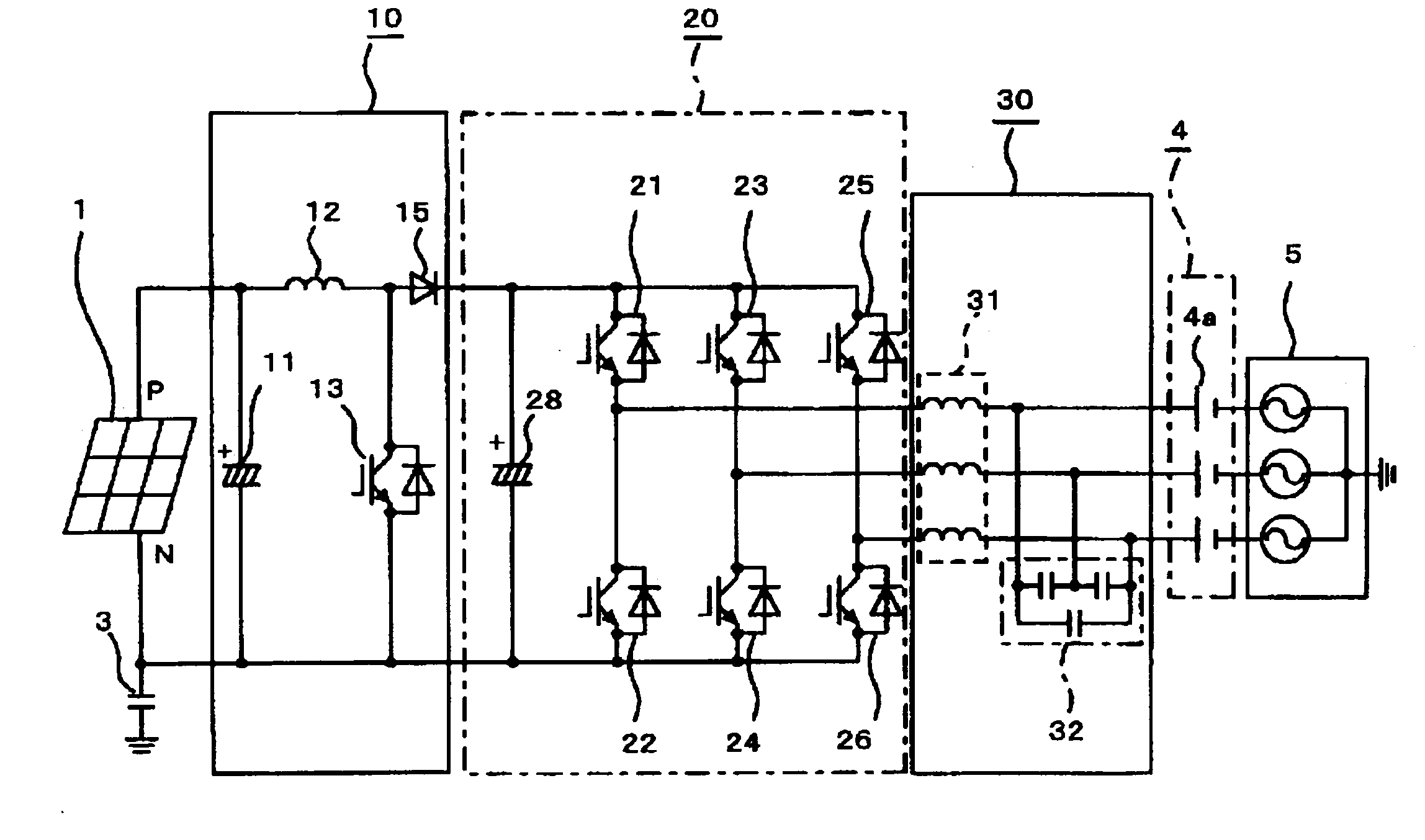
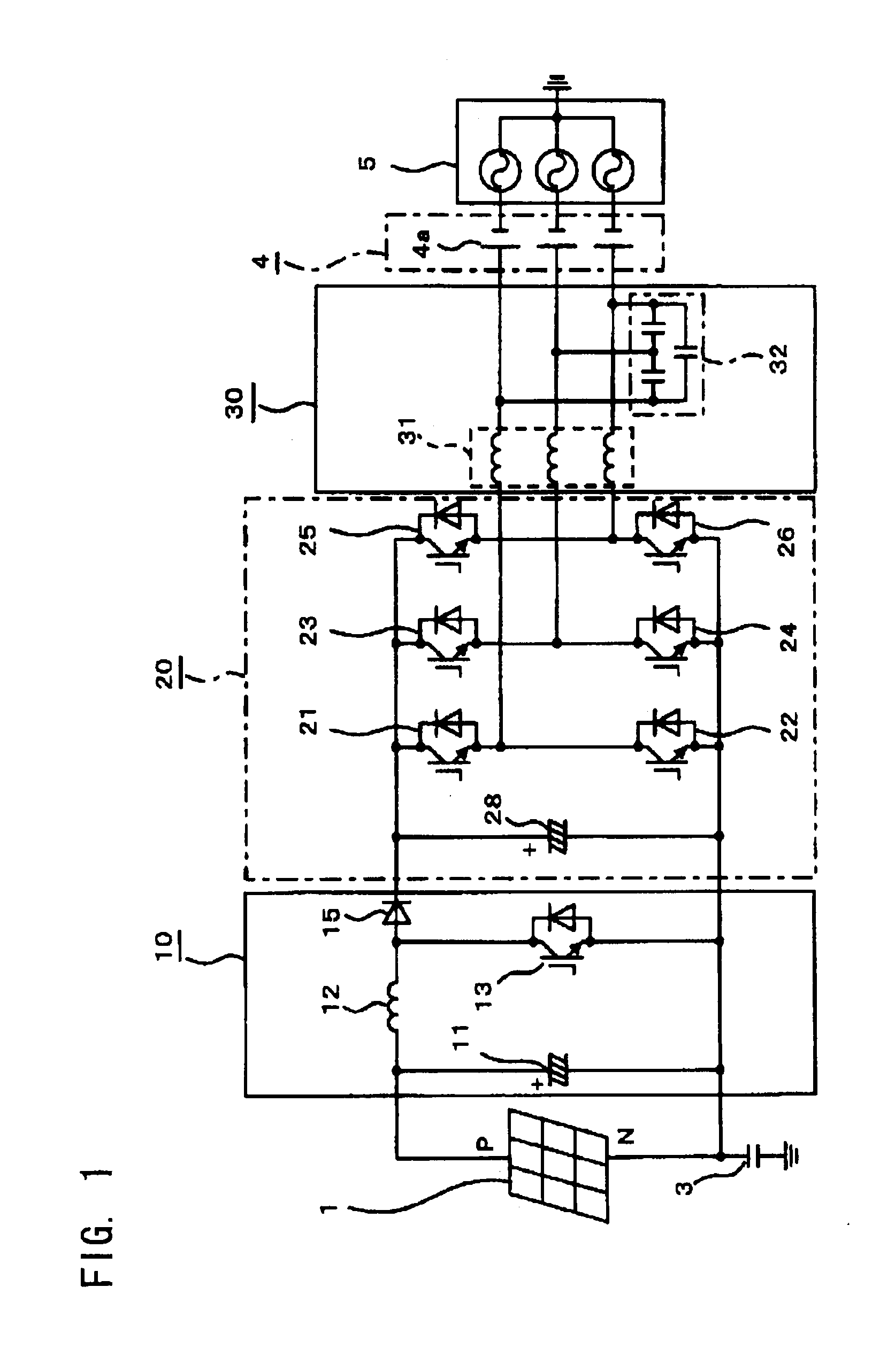
[0024]FIG. 1 is a diagram showing the configuration of a power conditioner for photovoltaic power generation according to embodiment 1 of the present invention. With reference to FIG. 1, DC power generated by a solar battery 1 of thin-film type is converted (stepped up) into DC power having a DC voltage of 2 E (V) which is a predetermined voltage, by a step-up chopper circuit 10. The DC power that has been stepped up is converted into three-phase AC power by an inverter circuit 20 which is a power conversion apparatus. The three-phase AC power is sent to an AC power supply system 5 via a sine wave filter 30 and an output DC voltage circuit 4 which is a bias application apparatus. The solar battery 1 is not grounded, and a negative electrode N of the solar battery 1 is grounded via an equivalent capacitor 3 having a floating capacitance Cs between the negative electrode N and the ground. The AC power supply system 5 is a three-phase star-connection AC power supply system in which pow...

embodiment 2

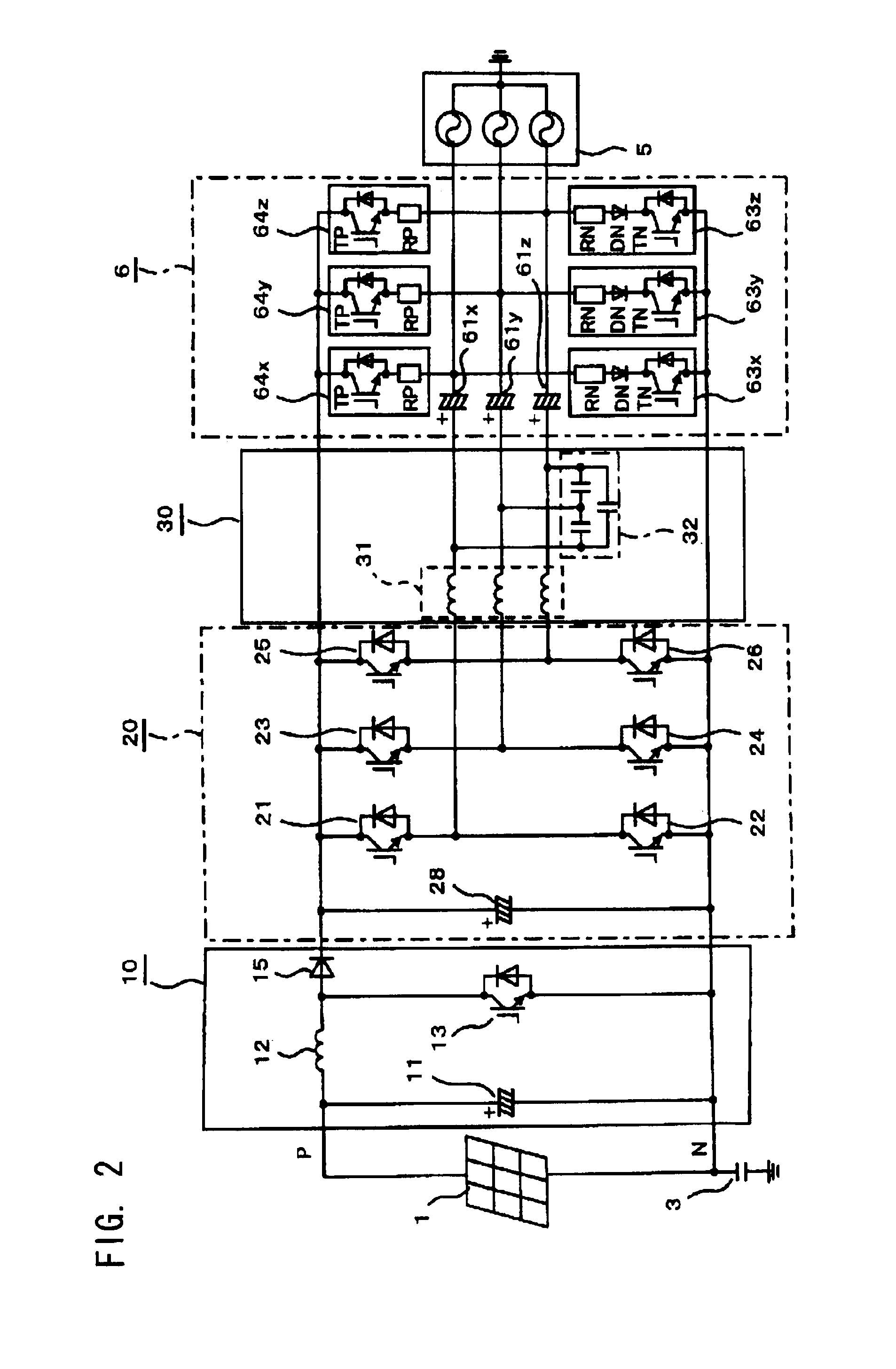
[0030]FIGS. 2 and 3 show embodiment 2. FIG. 2 is a diagram showing the configuration of a power conditioner for photovoltaic power generation, and FIGS. 3 to 6 are circuit diagrams for one phase (X-phase) for explaining charge / discharge operation. Although in embodiment 1, the case where the batteries 4a are connected in series has been described, capacitors may be used instead of the batteries 4a. Charge / discharge circuits for controlling the DC voltages of the capacitors are needed for the capacitors. With reference to FIG. 2, an output DC voltage circuit 6 includes: output capacitors 61x to 61z in place of the batteries 4a shown in FIG. 1; and charge circuits 63x to 63z and discharge circuits 64x to 64z for the output capacitors 61x to 61z for the respective phases. The output capacitors 61x to 61z are provided, for the respective phases, between the AC power supply system 5 and the filter reactors 31 of the sine wave filter 30 connected to the AC output side of the inverter circ...

embodiment 3

[0037]FIG. 7 is a diagram showing the configuration of a power conditioner for photovoltaic power generation according to embodiment 3. With reference to FIG. 7, output capacitors 71x to 71z, whose impedances are set at 5% of the impedance of the AC power supply system 5, are provided, for the respective phases, between the AC power supply system 5 and the filter reactors 31 of the sine wave filter 30, such that the positive electrodes of the output capacitors 71x to 71z are connected to the filter reactors 31. The other components are the same as those of embodiment 2 shown in FIG. 2. Therefore, the other components are denoted by the same reference numerals as in embodiment 2, and the description thereof is omitted. Since output currents flow in the output capacitors 71x to 71z, the terminal voltages of the output capacitors 71x to 71z vary. In addition, in the case of three-phase AC, there are phase differences among the variations in the terminal voltages. Ideally, it is desired...


PUM


Abstract

Power generated by a solar battery of thin-film type is stepped up to a predetermined DC voltage by a step-up chopper circuit, and the predetermined DC voltage is converted into three-phase AC power by an inverter circuit, and the three-phase AC power is supplied to an AC power supply system via an output DC voltage circuit. The solar battery is not grounded, and a negative electrode thereof has a floating capacitance between the negative electrode and the ground. The AC power supply system is configured by three-phase star-connection, and the neutral point is grounded. The output DC voltage circuit includes three batteries, and the batteries are provided, for the respective phases, between the AC power supply system and a sine wave filter connected to the AC output side of the inverter circuit. Therefore, it is possible to prevent acceleration of the deterioration of the solar battery.

Description

TECHNICAL FIELD[0001]The present invention relates to improvements in a power conditioner for photovoltaic power generation.BACKGROUND ART[0002]A power conditioner for photovoltaic power generation which coordinates a solar battery with an AC power supply system has a function of converting DC power generated by the solar battery into AC power, and a function of coordinating the solar battery with the AC power supply system. The AC power sent to the AC power supply system is consumed by a load connected to the AC power supply system. For example, a system coordination inverter as a power conditioner for photovoltaic power generation converts DC power inputted from a DC power supply (solar battery) into AC power via a converter circuit and an inverter circuit in which the inputs and outputs are not isolated from each other, and outputs the AC power to an AC power supply system that is grounded (see, for example, Patent Literature 1).[0003]In the above configuration, the solar battery...

Claims


Application Information

Patent Timeline
Patent Type & Authority Applications(United States)
IPC IPC(8): H02M7/537
CPCH01L31/02021Y02E10/563H02J3/383H02J2300/24H02J3/381Y02E10/56
Inventor TSUCHIYA, TAICHIROIWATA, AKIHIKOKAWAKAMI, TOMOYUKIOKUDA, TATSUYA
Owner MITSUBISHI ELECTRIC CORP
Why Eureka
Try Eureka