Supercharge Your Innovation With Domain-Expert AI Agents!

Methods and devices for forced air cooling of electronic flight bags

a technology for electronic flight bags and forced air cooling, which is applied in the direction of liquid fuel engines, machines/engines, instruments, etc., can solve the problems of electronic components, computer processors, and temperature control, and the reliability of motors such as those used in typical cooling fans is relatively low, and the electronics typically used in aerospace applications are prone to early failure,

Inactive Publication Date: 2012-05-17
ROSEMOUNT AEROSPACE INC
View PDF5 Cites 0 Cited by
  • Summary
  • Abstract
  • Description
  • Claims
  • Application Information

AI Technical Summary

Benefits of technology

This solution provides efficient heat removal with a favorable power dissipation to form factor ratio, protecting electronic components from contaminants and enabling easier maintenance, extending the time between EFB removal for maintenance and reducing the risk of premature failure.

Problems solved by technology

Temperature control for electronic components, and particularly computer processors, is an issue for computing devices like EFB's.
Since motors such as those used in typical cooling fans have a relatively low reliability compaired to electronics typically used in aerospace applications, fans are often not used in conventional EFB equipment because it is necessary to replace a typical cooling fan before what is considered a reasonable time to failure.
Moreover, in conventional EFB's using a cooling fan to blow air over electronic components can lead to early failure of an EFB if common contaminants like dust, moisture, or salt are entrained in the airflow.
Additionally, fans may of themselves also lead to early failure of EFB's.
Fans can fail due to vibration and temperature extremes, which reduces the Mean Time to Failure of an EFB.
Instead of cooling fans, many conventional EFB's employ elaborate passive cooling provisions which typically add cost and bulk to the design.
These traditional means for cooling EFB's may also result in a compromise in capability or reduced operating environmental limits.

Method used


Image

  • Methods and devices for forced air cooling of electronic flight bags
  • Methods and devices for forced air cooling of electronic flight bags
  • Methods and devices for forced air cooling of electronic flight bags

Examples


Embodiment Construction

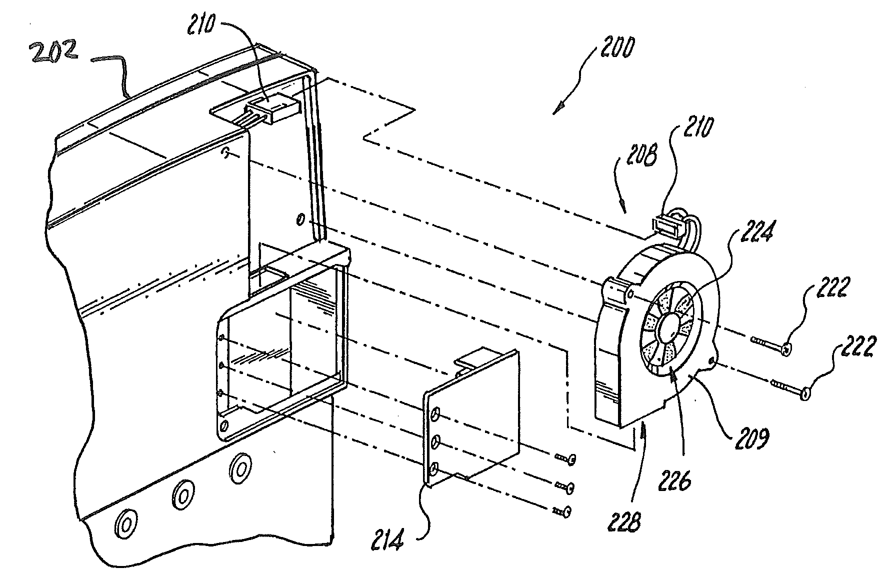
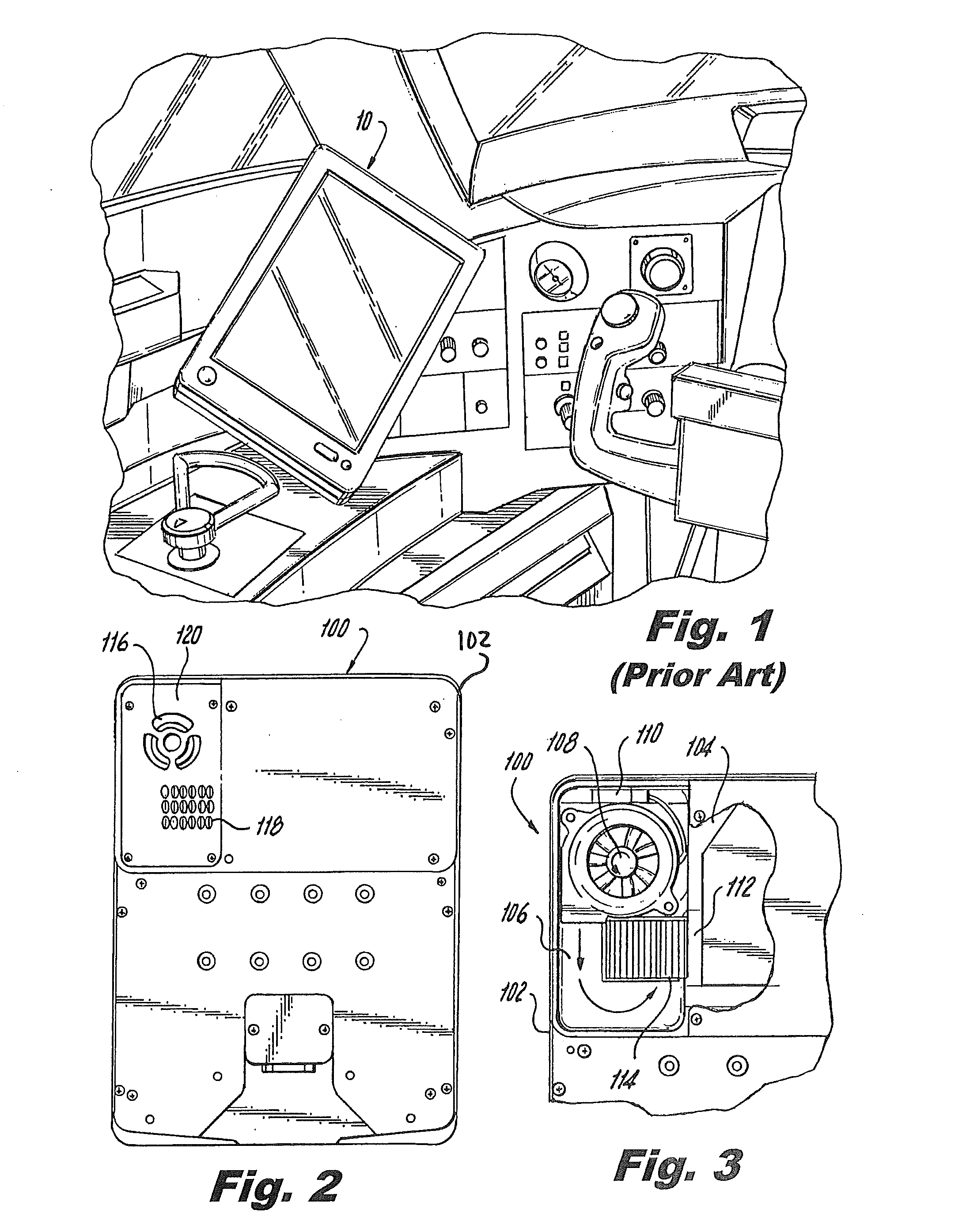
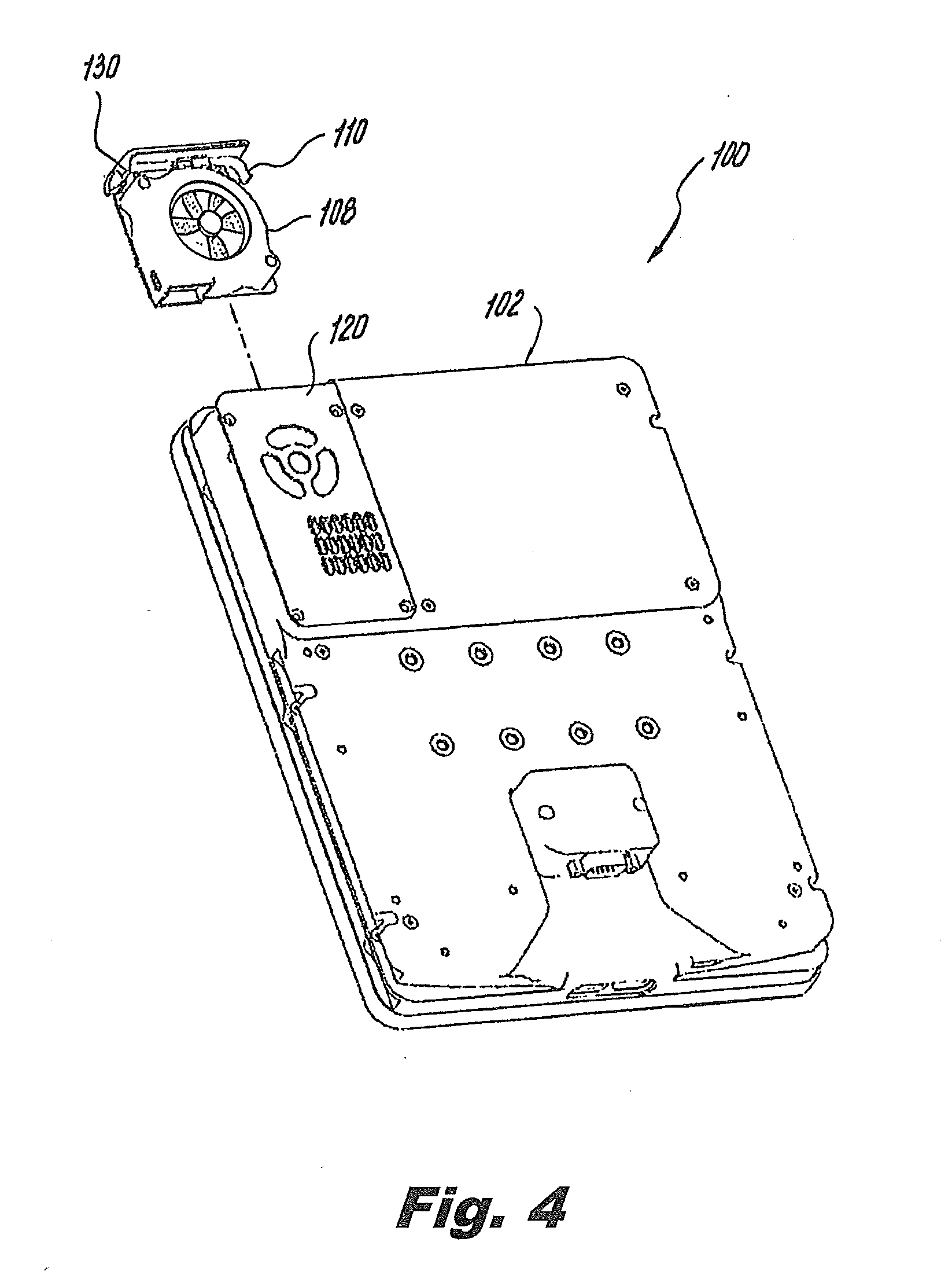
[0024]Reference will now be made to the drawings wherein like reference numerals identify similar structural features or aspects of the subject invention. For purposes of explanation and illustration, and not limitation, a partial view of an exemplary embodiment of an electronic flight bag in accordance with the invention is shown in FIG. 2 and is designated generally by reference character 100. Other embodiments of electronic flight bags in accordance with the invention, or aspects thereof, are provided in FIGS. 3-8, as will be described. The systems of the invention can be used for cooling electronic flight bag electronic components while providing a favorable form factor.

[0025]As shown in FIG. 1, an electronic flight bag computer (EFB) 10 is commonly used to replace the paper charts, manuals, and other references traditionally carried on board in pilots' flight bags. An EFB is a computer with a display for showing moving maps, weather patterns, technical data and other informatio...


PUM


Abstract

An electronic flight bag computer (EFB) includes a housing defining first and second compartments that are fluidly isolated from and in thermal communication with one another. The first compartment contains electronic components connected to a user interface on an exterior portion of the housing for providing interactive flight related computation functions to a user. The second compartment contains a forced convection cooling component in thermal communication with the electronic components. The forced convection cooling component directs a flow of cooling fluid into the second compartment to convey heat produced by the electronic components out of the housing, such that the cooling fluid in the second compartment remains fluidly isolated from the electronic components in the first compartment of the housing.

Description

BACKGROUND OF THE INVENTION[0001]1. Field of the Invention[0002]The present invention relates to cooling of electronic components, and more particularly to cooling systems for electronics onboard aircraft.[0003]2. Description of Related Art[0004]Electronic Flight Bags (EFB's) are computers used by aircraft crews as a replacement for the traditional flight bags containing charts and flight data formerly carried by pilots onto aircraft. An EFB provides electronic maps, weather information, and other information for use by flight crews in flying modern aircraft. A typical EFB is integrated with the cockpit and is not typically removed from the cockpit except for maintenance or replacement.[0005]Temperature control for electronic components, and particularly computer processors, is an issue for computing devices like EFB's. Various measures have been taken to maintain safe temperatures for electronic components in computers, which vary from application to application. Electronics used i...

Claims


Application Information

Patent Timeline
Patent Type & Authority Applications(United States)
IPC IPC(8): F01D15/00F01D25/24
CPCB64D2045/0075G06F1/203G06F1/1658
Inventor WICKS, CURTIS
Owner ROSEMOUNT AEROSPACE INC
Features
  • R&D
  • Intellectual Property
  • Life Sciences
  • Materials
  • Tech Scout
  • Unparalleled Data Quality
  • Higher Quality Content
  • 60% Fewer Hallucinations
Learn More