This helps you quickly interpret patents by identifying the three key elements:
Problems solved by technology
Method used
Benefits of technology
Benefits of technology
[0023]The present invention is able to provide a high performance turbine which is further reduced in the leakage flow rate of a fluid.
Problems solved by technology
However, leakage steam passing to the downstream side through the space at the leading end of the moving blade will not impart torque to the moving blade.
Method used
Image
Click on the blue label to locate the original text in one second.
Reading with bidirectional positioning of images and text.
Examples
first embodiment
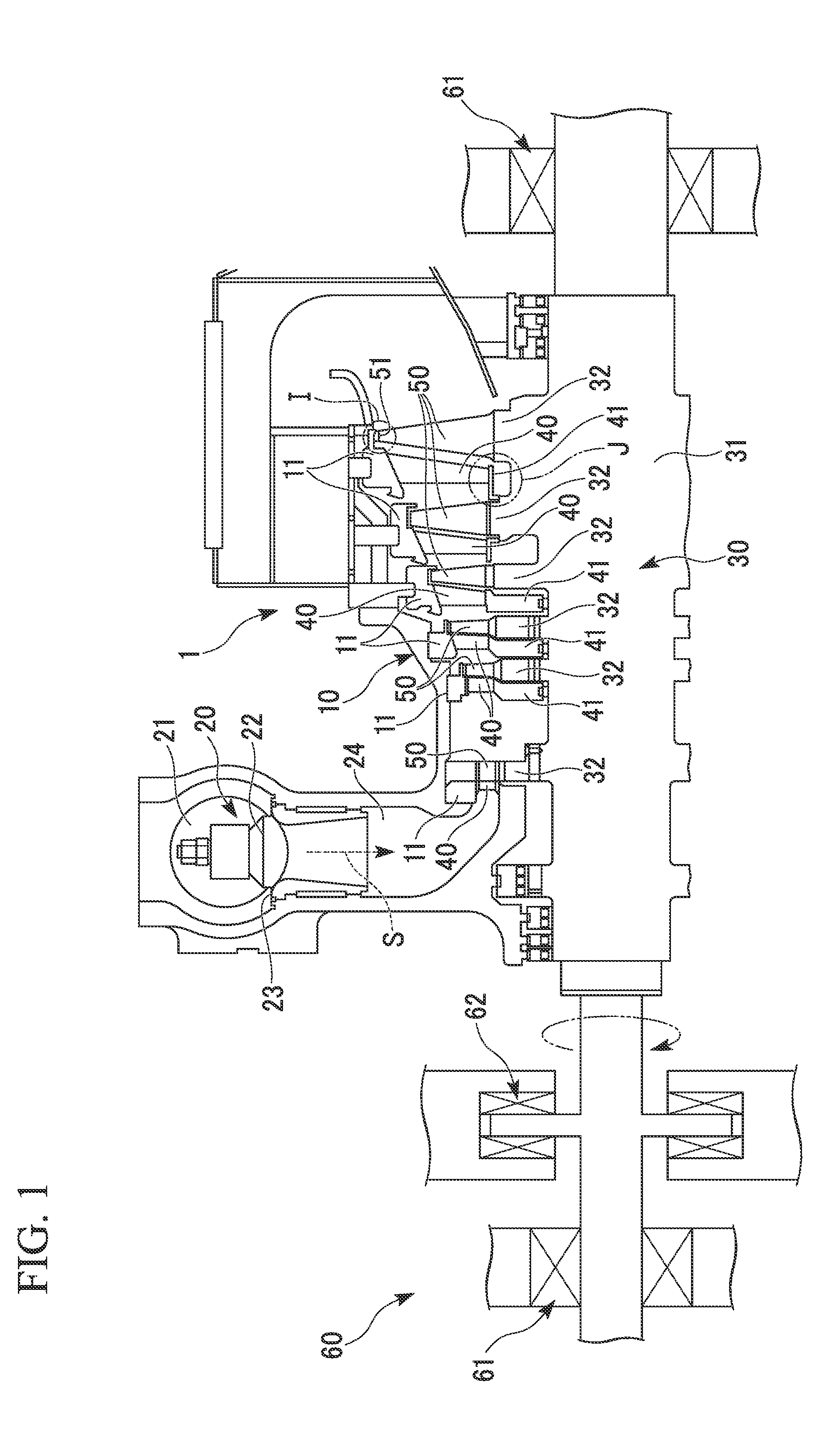
[0035]FIG. 1 is a schematic configuration sectional view which shows a steam turbine 1 of a first embodiment of the present invention.
[0036]The steam turbine 1 mainly includes the following configurations: a casing 10; a regulating valve 20 which regulates the amount and pressure of steam S flowing into the casing 10; a shaft body (rotor) 30 which is installed inside the casing 10 so as to rotate freely and transmits power to a machine such as a generator (not illustrated); a stationary blade 40 retained on the casing 10; a moving blade 50 installed on the shaft body 30; and a bearing part 60 which supports the shaft body 30 so as to be axially rotatable.
[0037]The casing 10 forms a flow channel of steam S, with an inner space sealed hermetically. A ring-shaped partition plate outer wheel 11 is firmly fixed on an inner wall surface of the casing 10. The shaft body 30 is arranged so as to penetrate the partition plate outer wheel 11. In the present embodiment, the partition plate oute...
second embodiment
[0088]Next, a description will be given of the steam turbine of the second embodiment of the present invention.
[0089]FIG. 8 is a drawing for describing the second embodiment. FIG. 8 is also a drawing corresponding to FIG. 2 which is an enlarged sectional view showing the major part I given in FIG. 1.
[0090]The second embodiment shown in FIG. 8 is different from the first embodiment shown in FIG. 2 in the following points. That is, in the first embodiment, the stepped parts 52 (52A to 52C) are formed on the tip shroud 51 which is the leading end of the moving blade (blade) 50, and the seal fins 15 (15A to 15C) are installed on the partition plate outer wheel (structure body) 11. On the other hand, in the second embodiment, stepped parts 52 are formed on a partition plate outer wheel (structure body) 11 and seal fins 15 are installed on a tip shroud 51.
[0091]That is, in the second embodiment, as shown in FIG. 8, two stepped parts 52 are formed on a groove bottom surface 11b of an annul...
third embodiment
[0102]Next, a description will be given of the steam turbine of the third embodiment of the present invention.
[0103]FIG. 9 is a drawing for describing the third embodiment and an enlarged sectional view which shows the major part J in FIG. 1. Further, FIG. 9 is a drawing corresponding to FIG. 2.
[0104]The third embodiment given in FIG. 9 is different from the first embodiment given in FIG. 2 in the following points. That is, in the first embodiment, the “blade” of the present invention is given as the moving blade 50, and the stepped parts 52 (52A to 52C) are formed on the tip shroud 51 which is the leading end of the moving blade. Further, in the first embodiment, the “structure body” of the present invention is given as the partition plate outer wheel 11 on which the seal fins 15 (15A to 15C) are installed. On the other hand, in the third embodiment, the “blade” of the present invention is given as a stationary blade 40 and stepped parts 52 are formed on the leading end of the stat...
PUM
Abstract
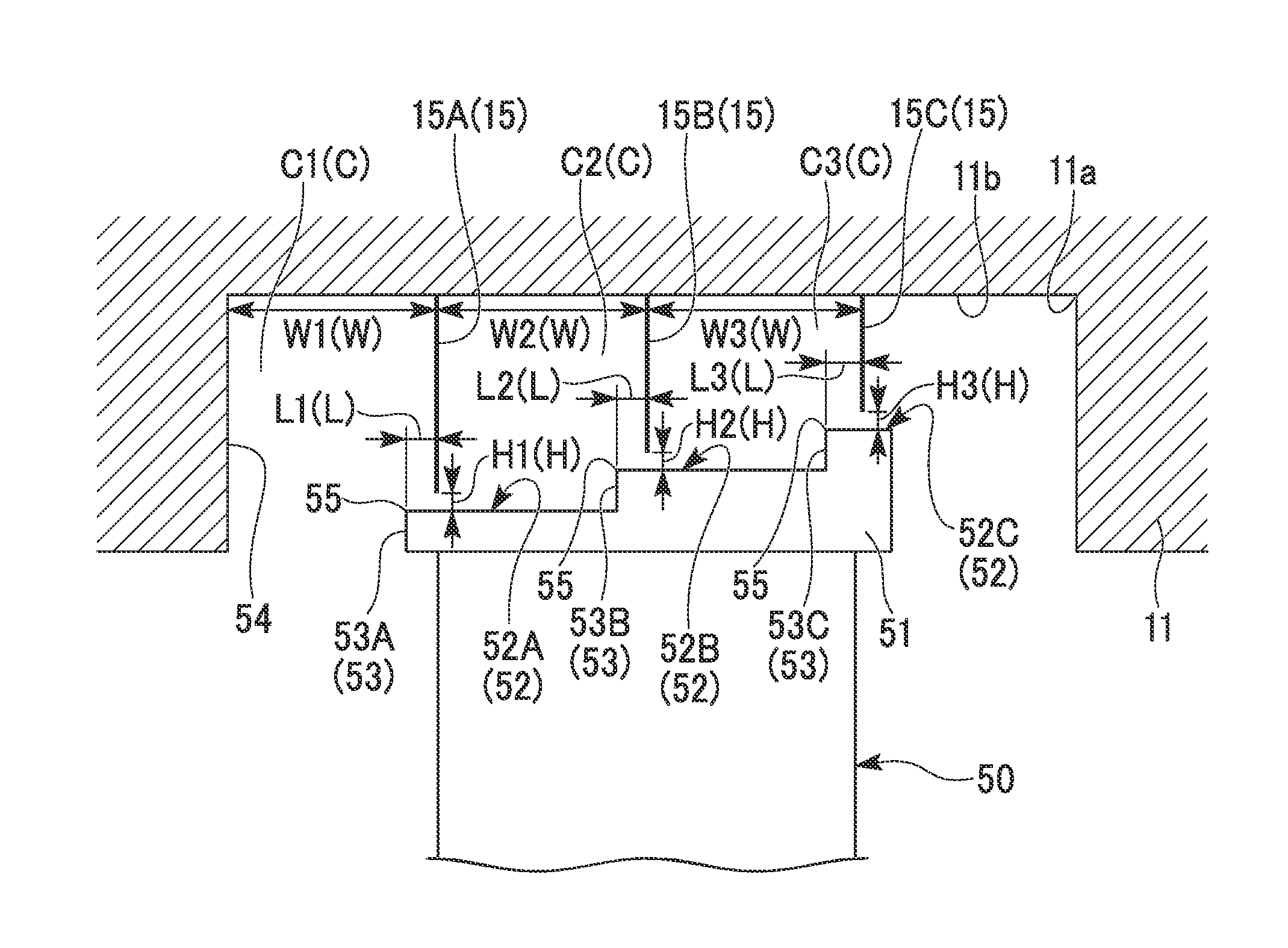
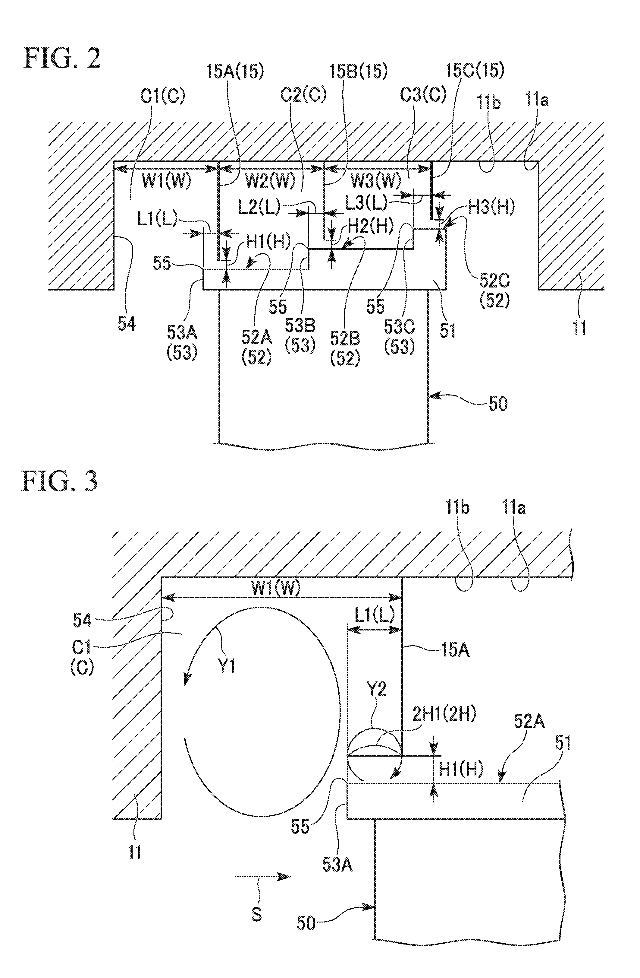
The turbine is provided with a blade (50) and a structure body (11) which rotates relatively with respect to the blade (50). A stepped part (52A) having a step surface (53A) is installed at one of the leading end of the blade (50) and the structure body (11) corresponding to the leading end thereof, while a seal fin (15A) which extends toward the stepped part (52A) to form a small space (H) is installed at the other of them. A cavity (C1) is formed between the blade (50) and the structure body (11) and also between the seal fin (15A) and the partition wall which faces thereto in the rotating shaft direction of the structure body (11) on the upstream side. When a distance of the cavity (C1) between the partition wall and the seal fin (15A) is given as a cavity width (W), and a distance between the seal fin (15A) and the end edge (55) of the stepped part (52A) in the rotating shaft direction on the upstream side is given as (L), at least one of the distances (L) satisfies the following formula (1).0.7H≦L≦0.3W (1)
Description
TECHNICAL FIELD[0001]The present invention relates to a turbine, for example, that used in power stations, chemical plants, gas plants, iron mills and marine vessels.[0002]The application concerned is to claim the right of priority to Japanese Patent Application No. 2009-235430 filed on Oct. 9, 2009 with the content included herein.BACKGROUND ART[0003]As is well known, there is available, as one type of steam turbine, that which is provided with a casing, a shaft body (rotor) installed inside the casing so as to be rotatable, a plurality of stationary blades arranged by being fixed to an inner circumference of the casing and a plurality of moving blades installed in a radial pattern on the shaft body on the downstream side of the plurality of stationary blades (downstream side of the flow of steam). Of these steam turbines, an impulse turbine converts pressure energy of steam to velocity energy by stationary blades and also coverts the velocity energy to rotational energy (mechanica...
Claims
Application Information
Patent Timeline
Application Date:The date an application was filed.
Publication Date:The date a patent or application was officially published.
First Publication Date:The earliest publication date of a patent with the same application number.
Issue Date:Publication date of the patent grant document.
PCT Entry Date:The Entry date of PCT National Phase.
Estimated Expiry Date:The statutory expiry date of a patent right according to the Patent Law, and it is the longest term of protection that the patent right can achieve without the termination of the patent right due to other reasons(Term extension factor has been taken into account ).
Invalid Date:Actual expiry date is based on effective date or publication date of legal transaction data of invalid patent.

