
Board connector

a board connector and connector technology, applied in the direction of coupling device connection, coupling device details, electric discharge lamps, etc., can solve the problem of tensile thin fixtures for weight saving, and achieve the effect of suppressing the width enlargement of fixtures and mounting grooves, preventing deformation of locks, and increasing the depth of housings

Active Publication Date: 2012-05-17
SUMITOMO WIRING SYST LTD
View PDF15 Cites 5 Cited by
  • Summary
  • Abstract
  • Description
  • Claims
  • Application Information

AI Technical Summary

Benefits of technology

The invention is a board connector with a housing and a fixture that can be mounted into the housing. The fixture has a plate surface and two locks that prevent detachment of the housing when fixed to a board. The fixture is made of metal and is mounted in the housing with the locks in contact with receiving surfaces to ensure a secure locking function. The fixture is designed to be wider to increase the fixing strength of the board connector without enlarging the housing. Reinforcing beads and mounting plates may be added for increased rigidity and reliability of the fixture. The technical effects of the invention are improved fixing strength and reliability of the board connector without enlarging the housing.

Problems solved by technology

On the other hand, there is a tendency to thin the fixtures for weight saving and the like.

Method used


Image

  • Board connector
  • Board connector
  • Board connector

Examples


Embodiment Construction

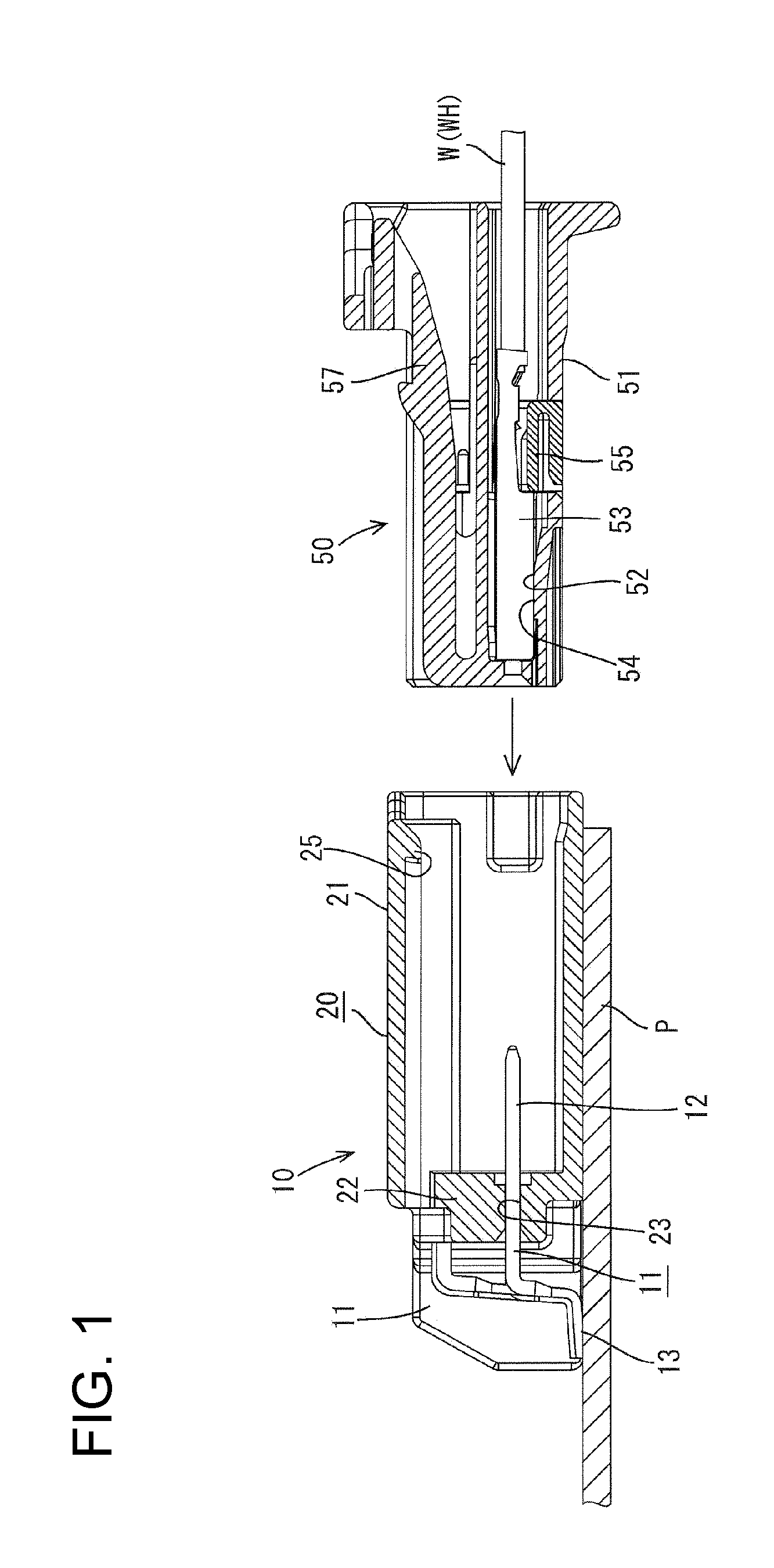
[0027]A board connector in accordance with the invention is identified by the numeral 10 in FIG. 1. The board connector 10 is to be fixed or mounted to an end part of an electric device or a board. such as a printed circuit board P and a harness-side connector 50 connected to an end of a wiring harness WH is connected to the board connector 10 from the front.

[0028]The board connector 10 includes a housing 20 made e.g. of synthetic resin and having terminal fittings 11 accommodated therein. Two fixtures 40 are mounted on opposite side surfaces of the housing 20 and are fixed to the board P by soldering, bolting, gluing or the like.

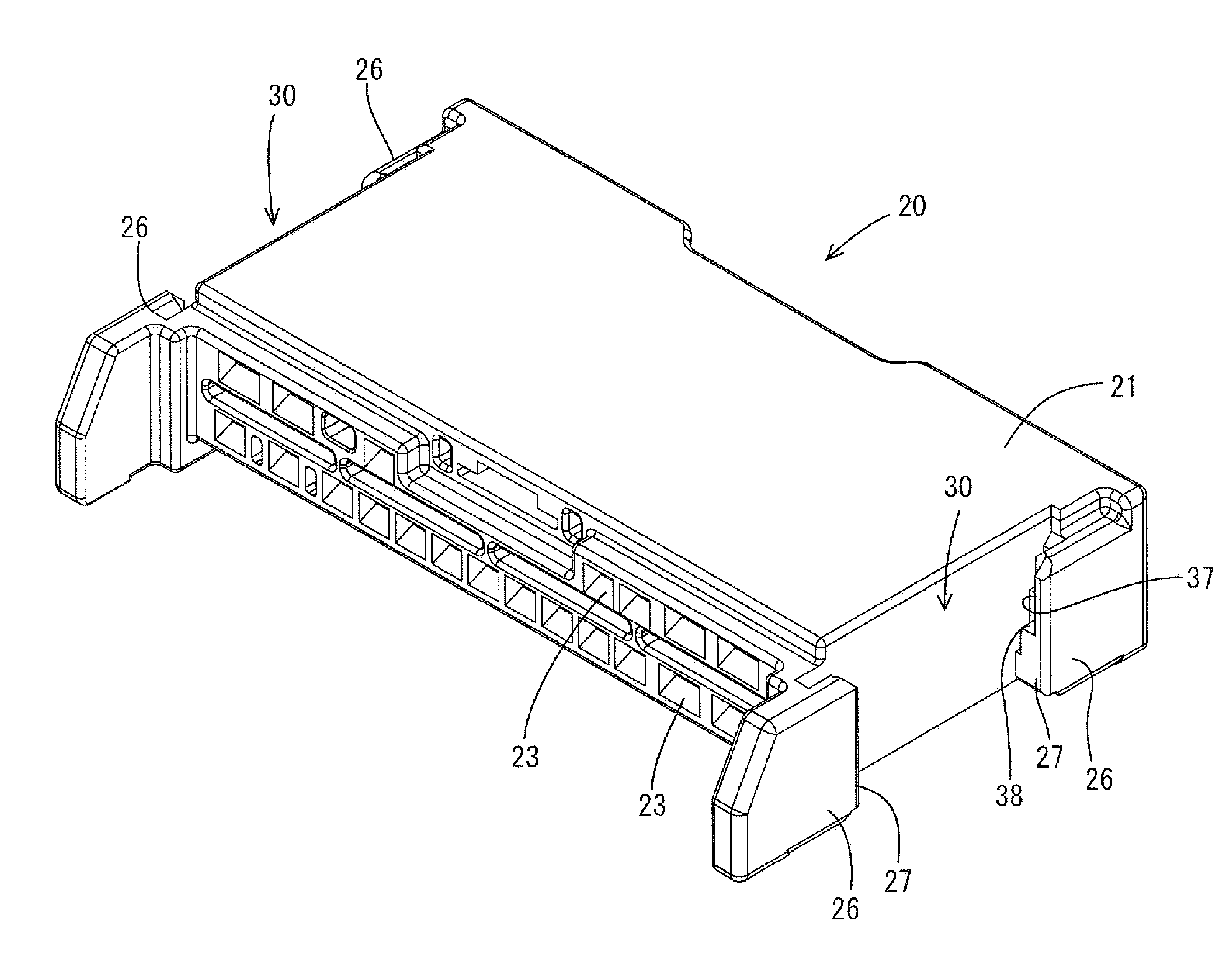
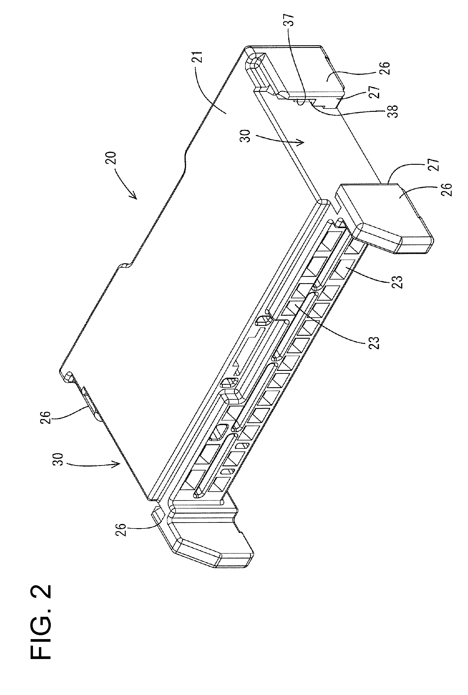
[0029]As also shown in FIG. 2, the housing 20 is substantially is in the form of a wide block and a receptacle 21 is formed at its front end for receiving the housing-side connector 50. Terminal insertion holes 23 are formed in upper and lower stages in a base wall 22 of the housing 20 at the back of the receptacle 21. Terminal connecting portions 12 at one...


PUM


Abstract

A board connector includes a housing (20) into which a mating connector (50) is to be fit, mounting grooves (30) formed on side surfaces of the housing (20), and metal fixing fixtures (40) to be mounted into the mounting grooves (30) while the plate surfaces thereof move along the side surfaces of the housing (20) and lower ends of which are to be fixed to a board (P). Projecting locks (43, 45) project laterally along the plate surface and a bent lock (44) bent outward substantially at a right angle with respect to the plate surface are arranged vertically one above another on each lateral edge of each fixing fixture (40). On the other hand, each mounting groove (30) includes receiving surfaces (35, 36, 38) that respectively contact with the projecting locks (43, 45) and the bent locks (44) to prevent downward movements of the locks.

Description

BACKGROUND OF THE INVENTION[0001]1. Field of the Invention[0002]The invention relates to a board connector.[0003]2. Description of the Related Art[0004]U.S. Pat. No. 7,134,910 discloses a board connector with a synthetic resin housing configured to receive a mating connector from the front. Mounting grooves are formed on side surfaces of the housing. Fixtures are mounted in mounting grooves and lower end portions of the fixtures are fixed to a circuit board by soldering. More specifically, the fixtures are formed by press-working a metal plate. Locks are formed at upper end portions of each fixture and project laterally from the opposite lateral edges. On the other hand, the mounting grooves each are formed to have a stepped shape with a widened upper end. The fixture is inserted into the mounting groove from above along the side surface of the housing, and a part of the fixture below the locks is pushed and press-fit into a narrow part of the mounting groove. This pushing operation...

Claims


Application Information

Patent Timeline
Patent Type & Authority Applications(United States)
IPC IPC(8): H01R24/76
CPCH01R12/707
Inventor AIHARA, TETSUYA
Owner SUMITOMO WIRING SYST LTD
Learn More