Low-carbon-type in-flight melting furnace utilizing combination of plasma heating and gas combustion, melting method utilizing the same and melting system utilizing the same

Inactive Publication Date: 2012-05-24
KOREA INST OF ENERGY RES
View PDF7 Cites 20 Cited by
  • Summary
  • Abstract
  • Description
  • Claims
  • Application Information

AI Technical Summary

Benefits of technology

[0024]The gas may be air or oxygen. The flames produced by plasma and gas may be a combination of a flame of about 10,000° C. resulting from plasma heating and a flame of about 2,000° C. resulting from gas combustion, and the in-flight. temper

Problems solved by technology

In addition, in the conventional melting furnaces, there is a problem in that the easily melting components (soda materials) and slowly melt

Method used


Image

  • Low-carbon-type in-flight melting furnace utilizing combination of plasma heating and gas combustion, melting method utilizing the same and melting system utilizing the same
  • Low-carbon-type in-flight melting furnace utilizing combination of plasma heating and gas combustion, melting method utilizing the same and melting system utilizing the same
  • Low-carbon-type in-flight melting furnace utilizing combination of plasma heating and gas combustion, melting method utilizing the same and melting system utilizing the same

Examples


Embodiment Construction

[0033]The foregoing and other objects, features and advantages of the present invention will become more apparent from the following description of embodiments with reference to the accompanying drawings. Hereinafter, specific embodiments of the present invention will be described in detail with reference to the accompanying drawings, in which like reference numerals indicate like elements.

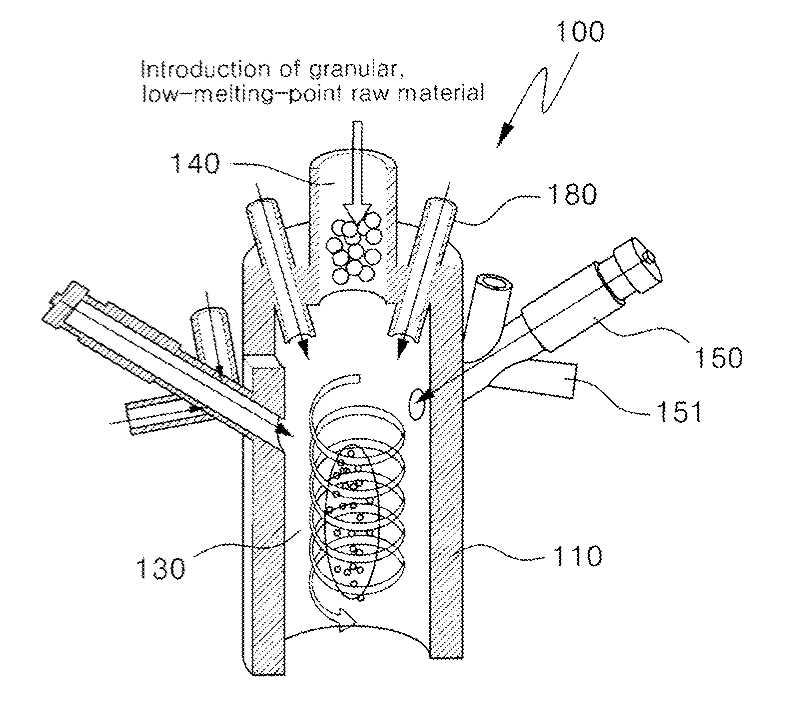
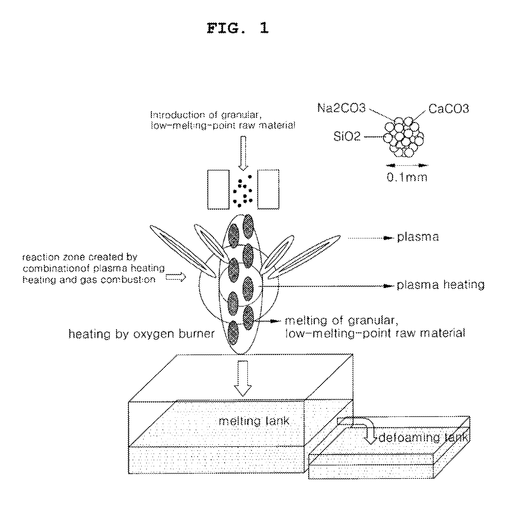
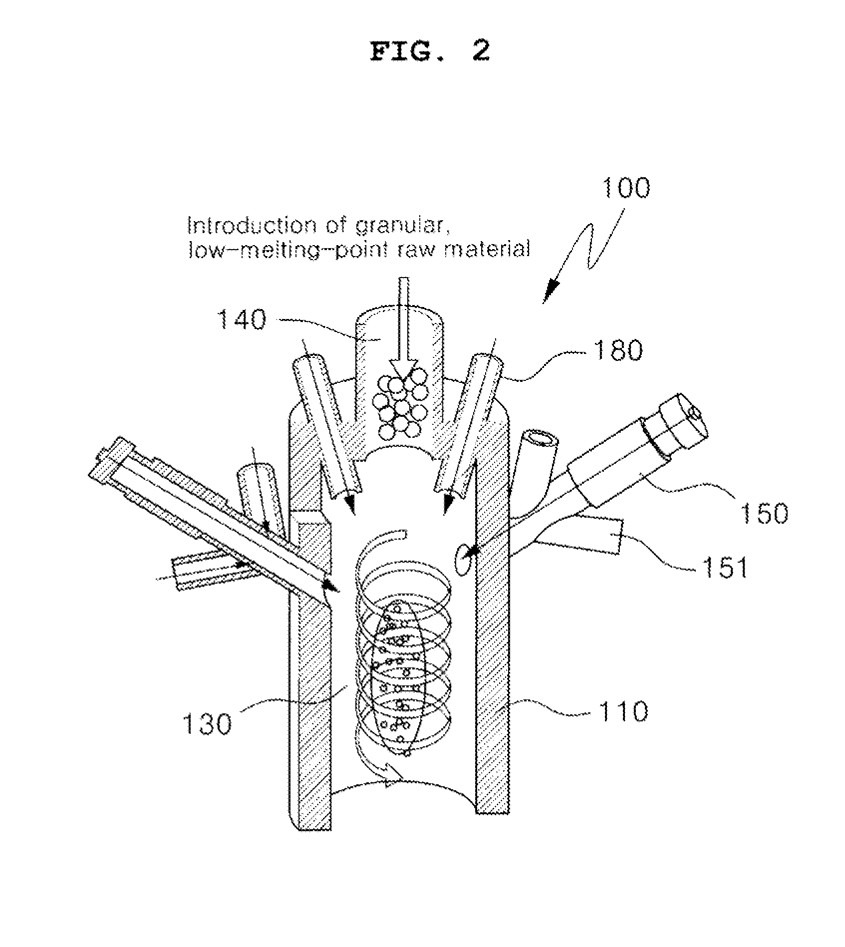
[0034]FIG. 1 is a conceptual view of a low-carbon-type in-flight melting furnace utilizing a combination of plasma heating and gas combustion according to one embodiment of the present invention; FIG. 2 illustrates the structure and principle of a low-carbon-type in-flight melting furnace utilizing a combination of plasma heating and gas combustion according to one embodiment of the present invention; and FIG. 3 is a schematic view of a low-carbon-type in-flight melting furnace utilizing a combination of plasma heating and gas combustion according to one embodiment of the present invention.

[0035]A...


PUM

PropertyMeasurementUnit
Temperatureaaaaaaaaaa

Abstract

A low-carbon-type in-flight melting furnace for melting granular raw material for glass production in in-flight state using plasma heating and gas combustion, a melting method using the same and a melting system utilizing the same are provided. The low-carbon-type in-flight melting furnace includes a melting furnace body unit; a melting tank in the melting furnace body unit; a melting unit provided above the melting tank and serving to melt raw material; a raw material feeding unit provided outside the melting unit; a plasma/gas melting device provided around the melting unit and serving to spray high-temperature flames produced by plasma and gas; an exhaust tube provided at one side of the melting tank and serving to discharge exhaust gas; and a tap hole for tapping the melt, formed in the melting unit, through the melting tank, in the form of a slag.

Description

CROSS REFERENCE TO RELATED APPLICATION[0001]This application claims the benefit under 35 U.S.C. 119(a) of Korean Patent Application No. 10-2010-0116070, filed on Nov. 22, 2010, the disclosure of which is incorporated by reference in its entirety for all purposes.BACKGROUND OF THE INVENTION[0002]1. Field of the Invention[0003]The present invention relates to a low-carbon-type in-flight melting furnace utilizing a combination of plasma heating and gas combustion, a melting method utilizing the same, and a melting system utilizing the same. Specifically, the present invention relates to a low-carbon-type in-flight melting furnace in which a granular raw material for glass production can be melted in an in-flight state using a combined technology of plasma heating and gas combustion, thus making desired glass compositions, including general-purpose glass and a frit for next-generation electronic devices, a method of melting using the low-carbon-type in-flight melting furnace and a melti...

Claims


Application Information

Patent Timeline
IPC IPC(8): C03B5/235C03B5/23C04B5/02C03B3/02
CPCC03B1/02C03B5/2353C03B5/025C03B3/026Y02P40/50
Inventor DONG, SANG KEUNKUM, SI WON
Owner KOREA INST OF ENERGY RES
Why Eureka
Try Eureka