Separating device for tubular flow-through devices

a flow-through device and separation device technology, applied in the direction of separation process, filtration separation, borehole/well accessories, etc., can solve the problems of low wear resistance, filter damage, extraction pipe damage, etc., and achieve the effect of improving wear or abrasion resistance and erosion resistance and reducing the tendency to fractur

Active Publication Date: 2012-05-24
3M INNOVATIVE PROPERTIES CO +1
View PDF22 Cites 8 Cited by
  • Summary
  • Abstract
  • Description
  • Claims
  • Application Information

AI Technical Summary

Benefits of technology

[0011]While overcoming the disadvantages of the prior art, the invention is based on the object of providing a separating device for tubular flow-through devices for removing sand and rock particles in the extraction of liquids or gases from deep wells or wells drilled in rock which has better wear or abrasion and erosion resistance and

Problems solved by technology

A major disadvantage of this construction is its low resistance to wear.
On account of the abrasive or erosive effect of the sand and rock particles flowing in at a high flow velocity, the filters are destroyed and the extraction pipes are damaged, in particular at the openings and valves.
At the same time, the productivity of the extraction decreases, since the sand is no longer effectively filtered out but is transported further with the extraction medium.
A further problem is the corrosive wear occurring on the filters and extraction pipes as a result of the use of treatment fluids.
This corrosive wear in turn exacerbates the abrasive wear.
One problem of the solutions described in these two documents is that, on account of their poor mechanical properties, filters of porous materials tend to fracture as a result of flexural loading.
The ultimate bending strength is generally well below 30% of that of the corresponding solid material and is therefore not sufficient for the mechanica

Method used


Image

  • Separating device for tubular flow-through devices
  • Separating device for tubular flow-through devices
  • Separating device for tubular flow-through devices

Examples


example 1

Resistance to Erosion

[0109]To determine the erosive wear, plates (about 75×75×15 mm) of coarse-grained, sintered silicon carbide ceramic (SSiC) of the type EKasic® C (ESK Ceramics GmbH & Co. KG) and of fine-grained, sintered silicon carbide ceramic (SSiC) of the type EKasic® F (ESK Ceramics GmbH & Co. KG) were subjected to a sand blasting test. A steel specimen served as a reference.

[0110]The tests were carried out by means of a sand blasting installation. Four different supporting materials that are typically used in offshore drilling operations served as blasting media: (1) 100 Mesh Frac Sand, (2) 16 / 20 Mesh Frac Sand, (3) 20 / 40 Mesh Frac Sand and (4) 20 / 40 Mesh Frac Sand High Strength. The blasting pressure was 2 bar and the blasting duration 2 hours, the jet being applied almost in the form of a point at an angle of 90° to the surface. The depth and width of the blasting impression characterize the erosive wear (see Table 1). The tests show that the sintered silicon carbide cera...

example 2

Resistance to Corrosion

[0111]Bars (about 3×4×25 mm) of coarse-grained silicon carbide ceramic of the type EKasic® C and of fine-grained silicon carbide ceramic of the type EKasic® F were subjected to a corrosion test.

[0112]Three bars of each type were immersed in the liquid to be investigated at 80° C. in a closable, heatable container for 14 days. Serving as liquids in this case were two different acid mixtures that are typically used in offshore drilling operations: (1) H2SO4, 70% and (2) HCl 12% / HF 2%. Following exposure, the changes in mass were determined to characterize the corrosive wear.

[0113]The tests show that the sintered silicon carbide ceramics have excellent corrosion resistance. Both EKasic® C and EKasic® F showed no measurable or detectable wear when exposed to HCl and H2SO4.

TABLE 2Results of the corrosion testsCorrosionExampleMaterialmediumLoss in mass %2.1EKasic ® F / CH2SO4, 70%not(SSiC)measurable2.2EKasic ® F / CHCl 12% / HFnot(SSiC)3%measurable

example 3

Flow-Through Test

[0114]A separating device was produced from a ceramic annular stack and subjected to a flow-through performance test in order to determine the pressure loss at different through-flow rates.
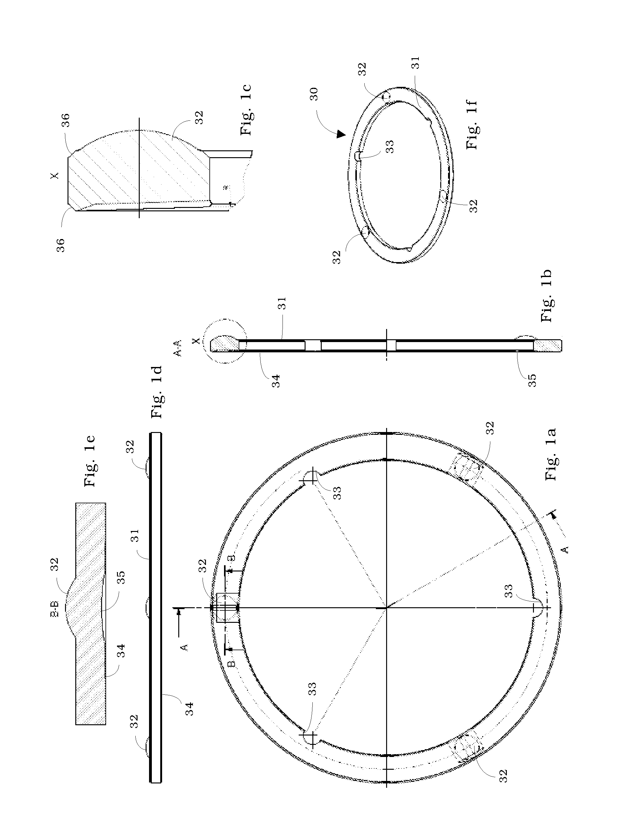
Rings

[0115]The annular disks have an outside diameter of 130 mm and an inside diameter of 109 mm. The ring height is optionally 3, 5 and 8 mm. The lower side is concavely curved, the radius of curvature is 2000 mm. The upper side is uncurved and planar with three spacers in the form of spherical caps with a radius R=25 mm. The gap height at the outside diameter is 0.25 or 0.45 mm. The annular disks are produced from silicon carbide.

Test Apparatus

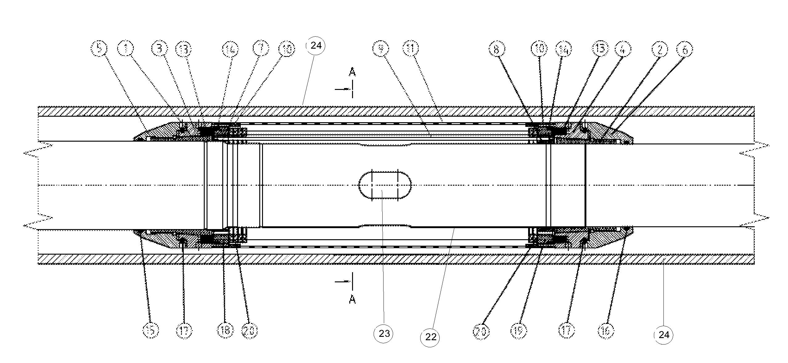
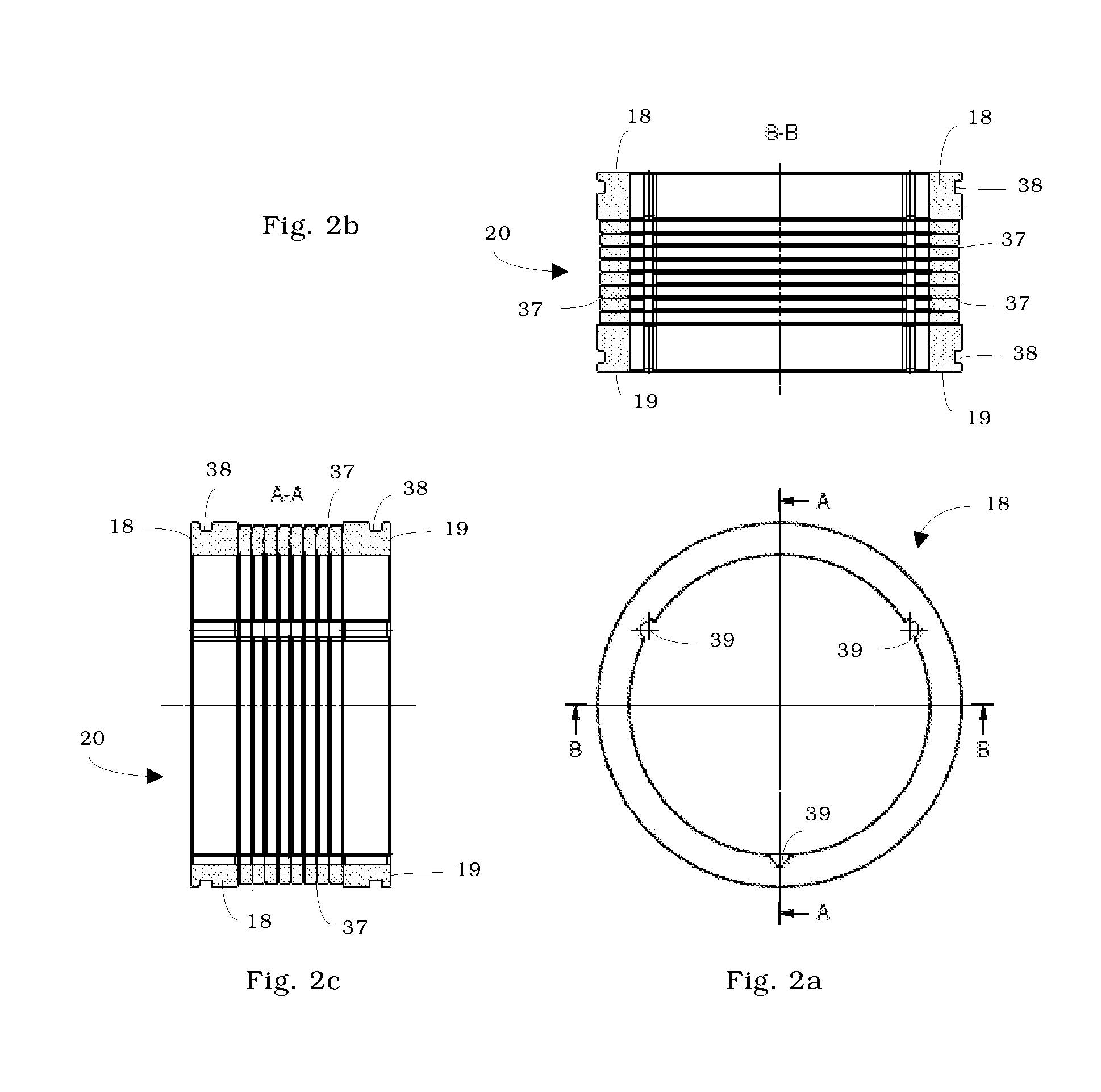
[0116]The test apparatus comprises an inner pipe, a stack of annular disks and an outer covering.

[0117]The inner pipe has a diameter of 101 mm and a length of 300 mm. In the middle of the lateral surface there are four openings (23 in FIG. 3), which are offset by 90° and through which the extracted medium can flow into the inner pipe. The ...


PUM

PropertyMeasurementUnit
Lengthaaaaaaaaaa
Lengthaaaaaaaaaa
Fractionaaaaaaaaaa

Abstract

The invention relates to a separating device for tubular flow-through devices (22) which serve for the extraction of liquids or gases from wells drilled in rock or deep wells, the separating device being suitable for the removal of sand and rock particles and comprising
    • an annular stack (20) of brittle-hard annular disks, the disks (30) being stacked and braced in such a way that a separating gap (37) for the removal of sand and rock particles is present in each case between the individual disks (30),
    • a coupling-on element (18, 19) at one or both ends of the annular stack (20),
    • a clamping device at one or both ends of the annular stack (20), making it possible on the one hand to flexibly brace the brittle-hard disks (30) and on the other hand to variably fasten the annular stack (20) on the tubular flow-through device (22).

Description

FIELD OF THE INVENTION[0001]The invention relates to a novel separating device with improved erosion and abrasion resistance, which is suitable for use for flow-through devices for the extraction of oil, water and gas mixtures or the individual components thereof, with the aid of which solids such as sand and rock particles can be removed from the liquids and gases to be extracted. The separating device serves in particular for preventing the erosive and abrasive wearing of the extraction equipment in deep wells by sand and rock particles. At the same time, the separating device is corrosion-resistant with respect to treatment fluids.BACKGROUND OF THE INVENTION[0002]For the extraction of liquids and gases, such as oil, water and gas mixtures or the individual components thereof, from reservoir rock, well equipment is used, substantially comprising an extraction pipe for conducting the extraction medium from the outside extraction point to the inner extraction pipe. This may be a per...

Claims


Application Information

Patent Timeline
IPC IPC(8): E21B43/02
CPCB01D29/46E21B43/08B01D46/406B01D39/2068E21B43/082
Inventor MUSSIG, SIEGFRIEDWAHRMANN, KLAUSWILDHACK, STEFANIEHOLZMULLER, BERNHARDJOLY, SAMUEL
Owner 3M INNOVATIVE PROPERTIES CO
Why Eureka
Try Eureka