Method for producing salt dust and salt dust generator

a technology of salt dust and generator, which is applied in the direction of medical atomisers, medical inhalators, inhalators, etc., can solve the problems of not being able to set the size of the filter in this prior-art technique, unable to provide an optimal, and rendering them useless for therapy purposes, etc., to achieve the effect of ensuring moisturisation and elastic skin, simple construction and accurate targeting

Active Publication Date: 2012-05-24
VIHERLAHTI KARI
View PDF3 Cites 3 Cited by
  • Summary
  • Abstract
  • Description
  • Claims
  • Application Information

AI Technical Summary

Benefits of technology

[0012]The salt particles generated by the method according to the disclosed embodiments are therapeutically useful, less than 5 micrometres in size. Therefore, the therapy provided by the method is safer and can be targeted more accurately than that with prior-art techniques. As an example of advantages obtained by using the method according to the present disclosure, it can be mentioned that salt dust that is dry and fine enough also penetrates efficiently into the periphery of the respiratory tract. Also, when entering the skin pores, the salt dust absorbs moisture from the surrounding air even better than before and thus keeps the skin moisturised and elastic.
[0013]An indisputable advantage is achieved also with a salt dust generator incorportating aspects of the disclosed embodiments because of its construction and operation principle. The milling of the salt particles in it is based in a simple mechanical procedure and the separation of the particles that are suitable for the therapy from the rest of the particles is based in physical event. Therefore, the apparatus according to the aspects of the disclosed embodiments has a simple construction and is easy to manufacture. This, in turn, is advantageous economically.

Problems solved by technology

The main disadvantage of the current techniques can be considered to be that a great proportion of the salt particles produced are larger than 5 micrometres in size, rendering them useless for purposes of the therapy.
Thus, a reasonable effort will not provide an optimal result with regard to the particle size of the salt.
It is evident that the size of the filter in this prior-art technique cannot be set so that only the particles of max 5 micrometres of size can penetrate through it because this would cause the filter to clog very soon.

Method used


Image

  • Method for producing salt dust and salt dust generator
  • Method for producing salt dust and salt dust generator
  • Method for producing salt dust and salt dust generator

Examples


Embodiment Construction

[0019]Below, exemplary embodiments of the disclosure will be described by way of an example of its structure and function, with reference to the above mentioned figures.

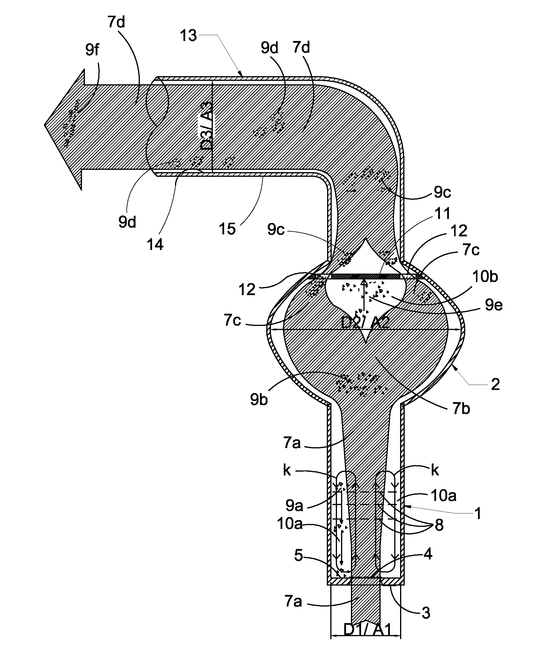
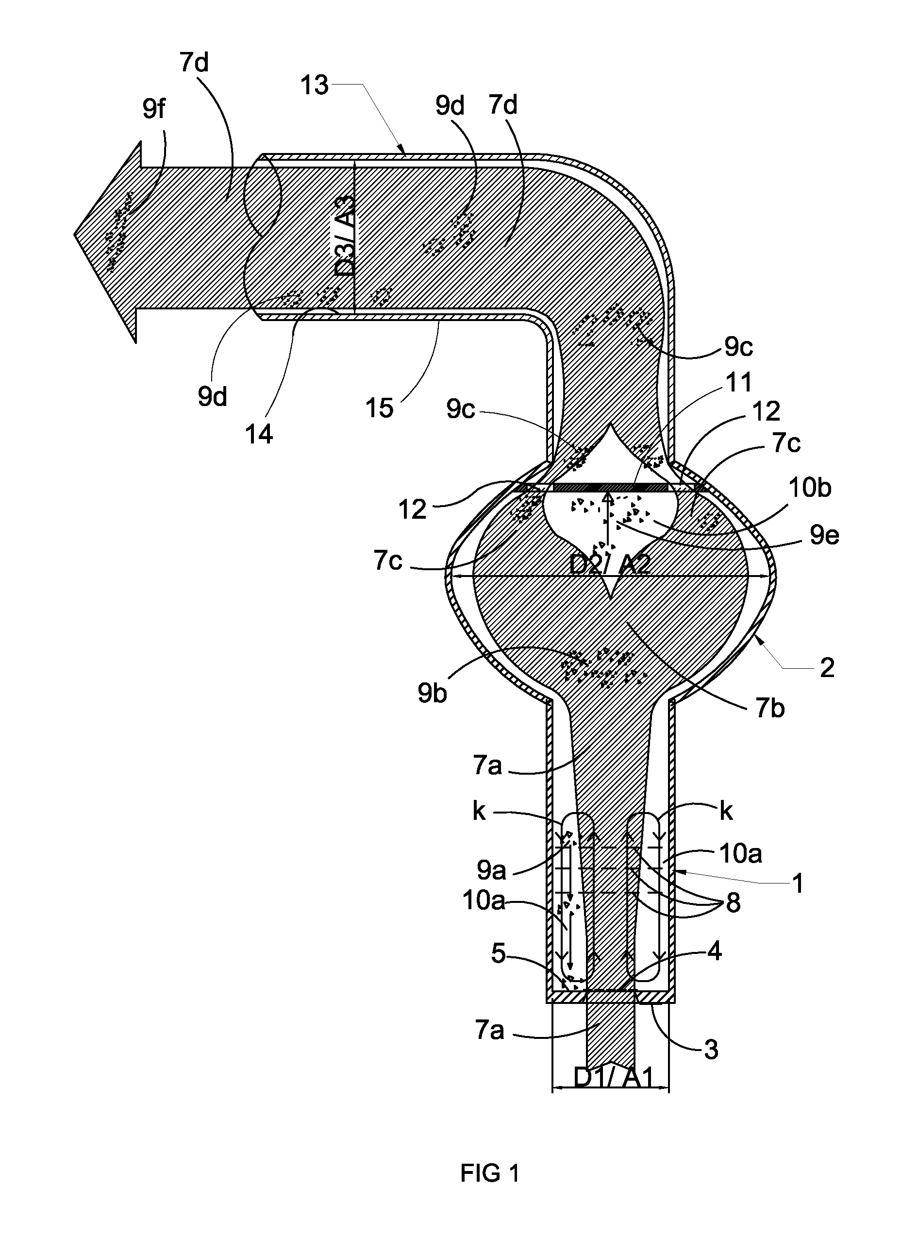
[0020]The salt dust generator, in one embodiment, is formed by a vessel 1 (FIG. 1) with a cylindrical shape standing in an upright position, preferably about 300 mm in height and the diameter Dl about 80 mm. Upon this vessel 1, there is a flow space 2 which in this example is essentially of the shape of an egg, the greatest diameter being about 250 mm. The bottom 3 of the vessel 1 is partially net. The net 4 is in the middle of the bottom covering about a half of the surface Al of the bottom 3 diameter D1. The material is solid in the peripheries of the bottom forming a ring like area 5. A layer of about 20 mm of granular salt 6 is placed upon the bottom 3 (FIG. 2). The salt particles are bigger than the mesh size of the middle part net 4 of the bottom 3 so that they remain inside the vessel 1. Air 7a is blown throug...


PUM


Abstract

A salt dust generator and method for producing salt dust that is used in salt therapy are described where salt dust is generated when salt particles that are moved in an air flow collide with each other and with certain parts of a salt dust generator. By regulating the speed of the air flow, thus changing its capability to carry the salt particles, and using obstacles, for instance nets that are placed into the salt dust generator vessel, it is possible to increase the amount of the collisions of the salt particles and thus make the formation of the salt dust more efficient.

Description

BACKGROUND[0001]1. Field[0002]The present disclosure relates to salt therapy systems, and in particular to a method for producing fine salt dust in the breathing air by means of a device producing salt dust, i.e. salt dust generator—and the salt dust generator used in the present method.[0003]2. Brief Description of Related Developments[0004]The method and the generator in accordance with aspects of the disclosed embodiments are used for example in salt room therapy, wherein fine salt dust is blown by a salt dust generator into a room lined with salt. The salt dust provides the room air with negatively charged particles that, when inhaled, have infection reducing and phlegm detaching influence in the respiratory tract, thus opening the tract and easing respiration. In salt room therapy, the amount of salt that reaches the body system is so small that it does not cause additional swelling or adverse increase in blood pressure. Typically, a treatment session takes about 40 minutes at ...

Claims


Application Information

Patent Timeline
Patent Type & Authority Applications(United States)
IPC IPC(8): B02C19/00
CPCA61M11/02A61K9/0075A61P11/10A61P31/00A61M13/00A61M15/0086A61M15/02A61G10/00A61K9/00A61K33/14
Inventor VIHERLAHTI, KARI
Owner VIHERLAHTI KARI
Why Eureka
Try Eureka