Organic electroluminescent element and method for producing the same

a technology of electroluminescent elements and organic solvents, which is applied in the direction of thermoelectric device junction materials, electrical equipment, and semiconductor devices, etc., can solve the problems of inability to improve the adhesiveness, the performance of the resultant element may be adversely affected by the residual solvent in the functional layers, and the durability of the element cannot be improved. , to achieve the effect of high interlayer adhesiveness and durability

Inactive Publication Date: 2012-05-24
UDC IRELAND
View PDF2 Cites 16 Cited by
  • Summary
  • Abstract
  • Description
  • Claims
  • Application Information

AI Technical Summary

Benefits of technology

[0032]The present invention can provide an organic electroluminescent element having high interlayer adhesiveness and durability, and a method for producing the organic electroluminescent element.

Problems solved by technology

However, there still are problems on durability of elements, and various attempts have been made to improve durability for actual use.
In this case, however, the functional layers are formed by applying functional layer-forming materials through ink jetting, followed by drying, and they are difficult to be thin layers and also, there are concerns that the performances of the resultant element may be adversely affected by the residual solvent in the functional layers.
However, there is no description on the conditions for improving the adhesiveness of the different layers in this organic electroluminescent element, and thus the adhesiveness cannot be improved.
However, there are not disclosed proper conditions of the thickness and roughness of the functional layers for improving adhesiveness.
Thus, at present, there has yet not been an organic electroluminescent element having satisfactorily excellent durability.

Method used


Image

  • Organic electroluminescent element and method for producing the same
  • Organic electroluminescent element and method for producing the same
  • Organic electroluminescent element and method for producing the same

Examples


example 1

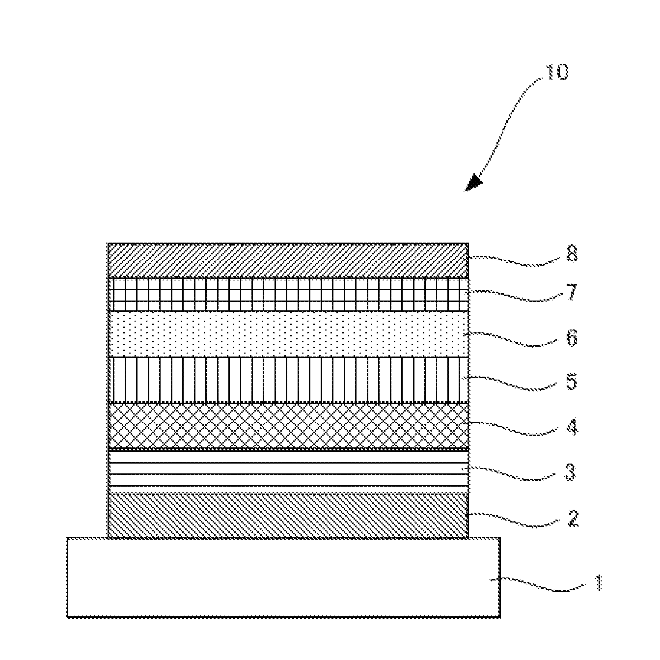
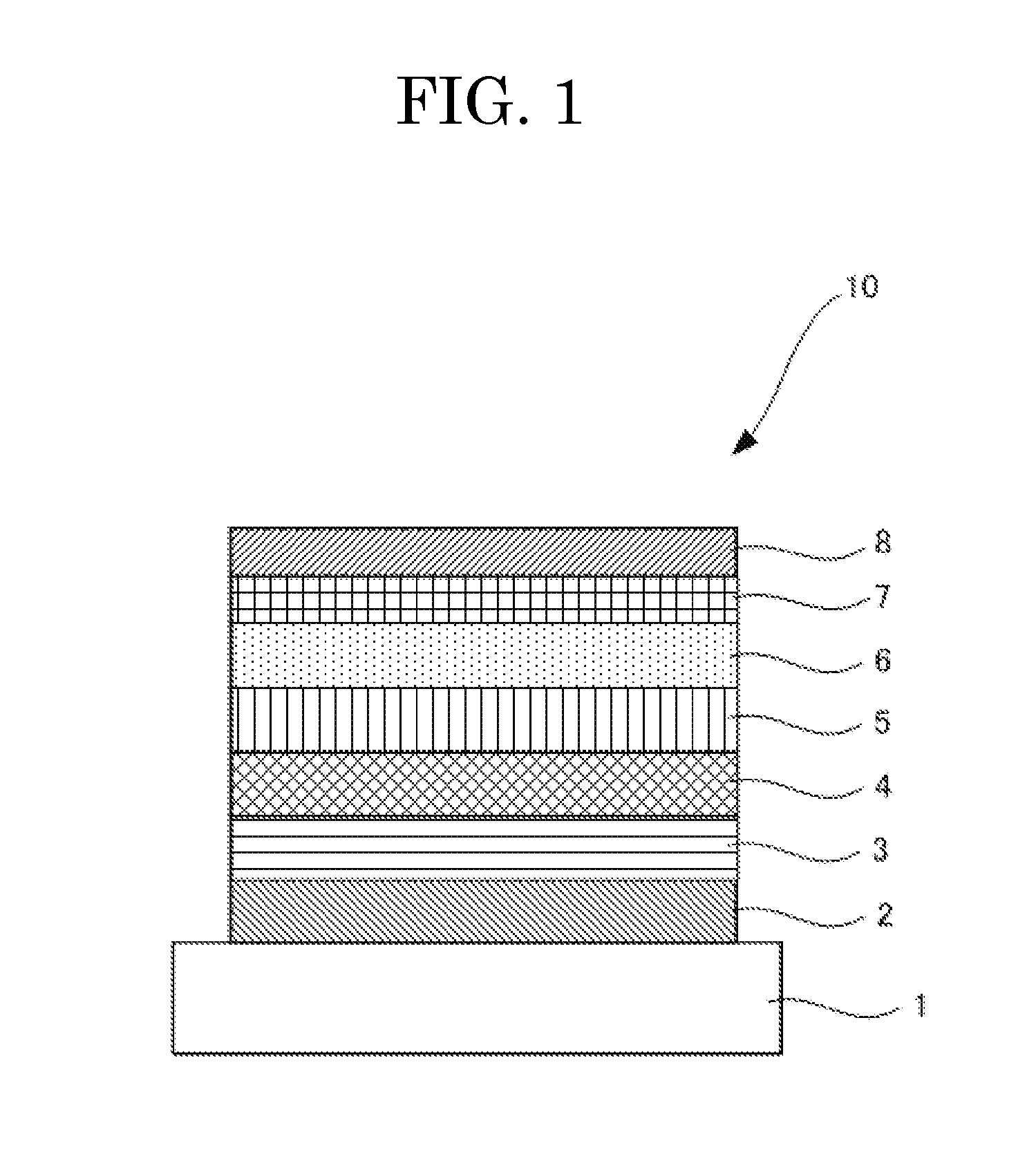
[0148]A glass substrate, 0.5 mm thickness and 2.5 cm×2.5 cm, was placed in a washing case, where it was ultrasonically washed in 2-propanol. The thus-washed glass substrate was subjected to UV-ozone treatment for 30 minutes. Onto the resulting glass substrate, each layer described below was deposited by the vacuum deposition method.

[0149]The deposition was conducted using a vacuum deposition apparatus (product of Tokki Corporation) and, unless otherwise specified, the deposition rate was 0.2 nm / s The deposition rate and the thickness of each layer were determined by measuring, using a film thickness monitor (CRTM-9000, product of Ulvac, Inc.), the deposition rate of the deposition material on a crystal oscillator located distant by the same distance as that between the deposition source and the substrate.

[0150]Also, the surface roughness Ra of the deposition layer was an average of five measurements which were obtained by measuring a 2 μmm×2 μm measurement region five times on a tap...

example 2

[0161]An organic electroluminescent element of Example 2 was produced in the same manner as in Example 1, except that the following hole transport material 2 was used instead of the hole transport material 1 to form the second hole transport layer.

example 3

[0162]An organic electroluminescent element of Example 3 was produced in the same manner as in Example 1, except that the following hole transport material 3 was used instead of the hole transport material 1 to form the second hole transport layer.


PUM


Abstract

An organic electroluminescent element including: a first electrode; at least one organic deposition layer; and a second electrode, the first electrode, the organic deposition layer, and the second electrode being formed in this order, wherein the organic deposition layer satisfies the relationship 0.093<Ra/t<0.340 where Ra denotes a surface roughness of a surface of the organic deposition layer, the surface being at the side of the second electrode, and t denotes a thickness of the organic deposition layer.

Description

TECHNICAL FIELD[0001]The present invention relates to an organic electroluminescent element having excellent durability and a method for producing the organic electroluminescent element.BACKGROUND ART[0002]Organic EL elements have advantageous features such as self emission and high-speed response, and are expected for the application to flat panel displays. In particular, since such an organic electroluminescent element was reported that has a dual-layer structure (lamination type) in which a hole-transporting organic thin film (hole transport layer) is laminated on an electron-transporting organic thin film (electron transport layer), organic electroluminescent elements have been attracting attention as a large-area light-emitting element that emits light at a low voltage of 10 V or lower.[0003]However, there still are problems on durability of elements, and various attempts have been made to improve durability for actual use.[0004]For example, there has been disclosed an organic ...

Claims


Application Information

Patent Timeline
Patent Type & Authority Applications(United States)
IPC IPC(8): H01L51/54H01L51/56
CPCH01L51/0072H01L51/5048H01L51/5016H01L51/0087H10K85/346H10K85/6572H10K50/14H10K50/11H10K2101/10H10K50/15
Inventor SATO, TASUKUKAMINAGA, KUNIYUKIHAYASHI, MASAYUKITSUTSUMI, KIYOHIKOFUJITA, MITSUHIRO
Owner UDC IRELAND
Why Eureka
Try Eureka