Layered-modeling device and method using said device for manufacturing three-dimensional objects

a technology of layered model and irradiation method, which is applied in the direction of manufacturing tools, electric/magnetic/electromagnetic heating, additive manufacturing processes, etc., can solve the problems of deterioration of machining accuracy, further deterioration of reduced output of light beam focusing, so as to facilitate the elimination of fumes inside the chamber and improve the positional accuracy of irradiation with light beam

Inactive Publication Date: 2012-05-24
PANASONIC INTELLECTUAL PROPERTY MANAGEMENT CO LTD
View PDF3 Cites 132 Cited by
  • Summary
  • Abstract
  • Description
  • Claims
  • Application Information

AI Technical Summary

Benefits of technology

[0040]According to the present invention, it is possible to provide a method for manufacturing a three-dimensional shaped object, which is capable of easily eliminating fumes inside the chamber, so as to improve a positional accuracy of irradiation with a light beam and a machining accuracy.

Problems solved by technology

However, in such a manufacturing method, the chamber is easily filled with fumes generated during sintering or melting and subsequent solidification, and fumes easily adhere to a window.
However, it takes time to replace the fumes with the ambient gas, and a light beam scatters due to the filled fumes or the fumes adhering to the window, which has brought about the problem of decreased output and decreased degree of focusing of the light beam, and of deterioration in machining accuracy because of deterioration in positional accuracy of irradiation with the light beam.
Further, there has been the problem that the light beam is absorbed into the fumes adhering to the window to raise a temperature of the window, which thermally deforms the window to further deteriorate the positional accuracy of irradiation.

Method used


Image

  • Layered-modeling device and method using said device for manufacturing three-dimensional objects
  • Layered-modeling device and method using said device for manufacturing three-dimensional objects
  • Layered-modeling device and method using said device for manufacturing three-dimensional objects

Examples


Embodiment Construction

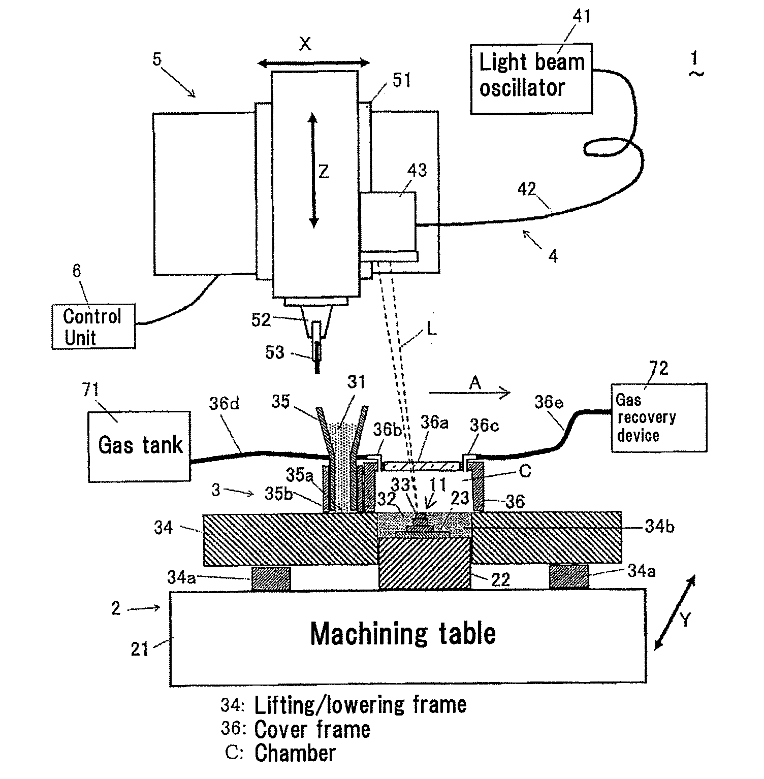
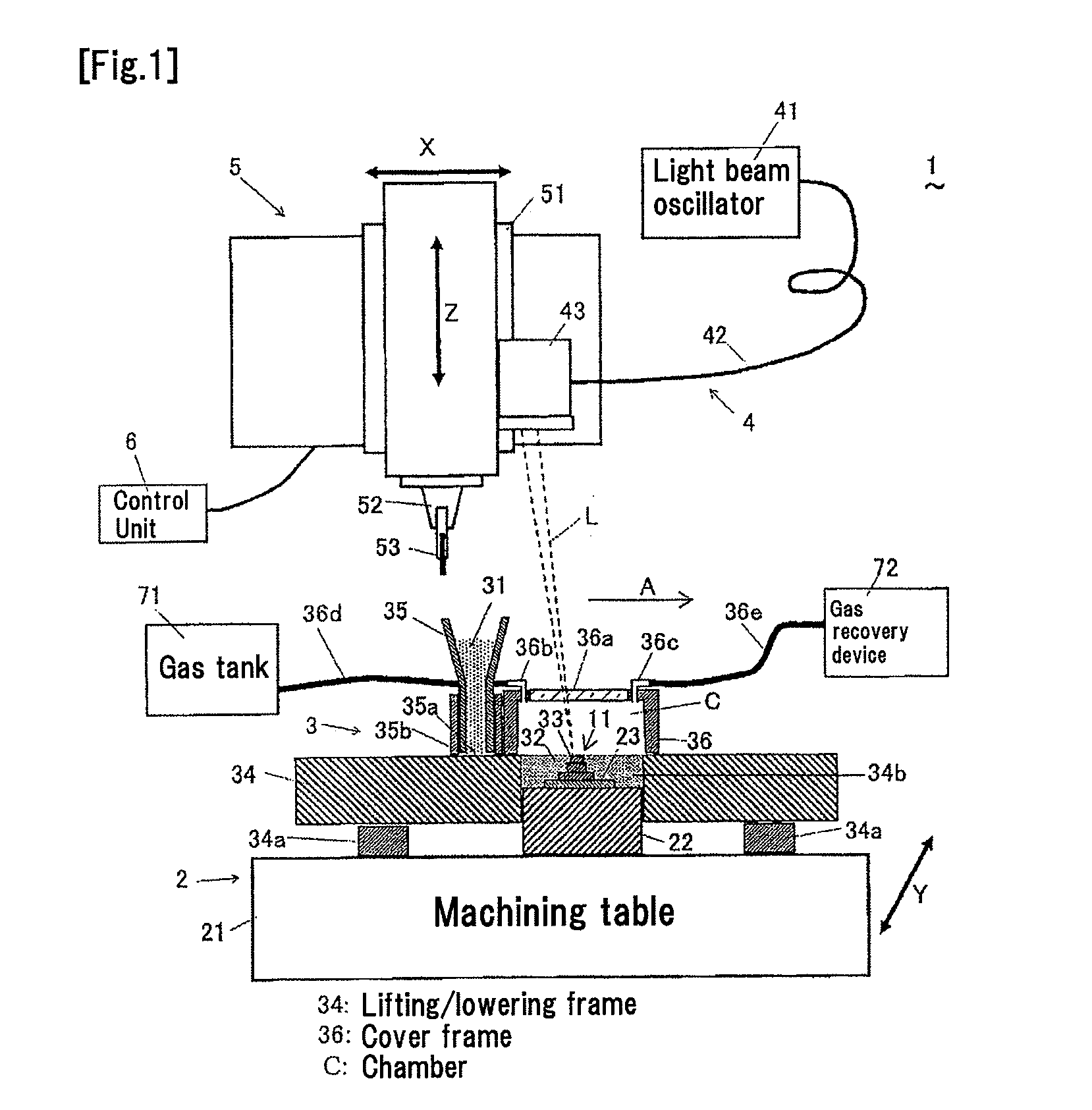
[0067]A method for manufacturing a three-dimensional shaped object according to an embodiment of the present invention will be described with reference to the accompanying drawings. FIG. 1 shows a constitution of a stacked-layers forming device (hereinafter referred to as the present device) used for the manufacturing method. The present device 1 comprises: a shaping unit 2 that shapes a shaped object 11 having a three-dimensional shape; a powder layer forming unit (powder layer forming means) 3 that supplies a powder material 31 to form a powder layer 32; a light beam irradiating unit 4 that irradiates the powder layer 32 with a light beam L to form a solidified layer 33; a milling and removal tool 5 that performs milling operation in the vicinity of the circumference of the shaped object 11; and a control unit 6 that controls operations of the respective units. The powder layer 32 is irradiated with the light beam L, thereby allowing sintering or melting and subsequent solidificat...


PUM

PropertyMeasurementUnit
grain diameteraaaaaaaaaa
porosityaaaaaaaaaa
thicknessaaaaaaaaaa

Abstract

An object of the present invention is to easily eliminate fumes inside a chamber, so as to improve a positional accuracy of irradiation with a light beam and a machining accuracy in a method for manufacturing a three-dimensional shaped object. A stacked-layers forming device 1 includes a powder layer forming unit 3, a light beam irradiating unit 4, a base 22 which is fixed and on which a powder layer 32 is formed, a lifting/lowering frame 34 which surrounds the circumference of the base 22 and is freely capable of being lifted and lowered, a cover frame 36 which has a window 36a allowing transmission of light beam in its top surface, and whose bottom surface is opened, and which is disposed on the lifting/lowering frame 34 to form a chamber C, and a gas tank 71 for supplying an ambient gas. The lifting/lowering frame 34 is lowered to reduce the volume of the chamber C, so as to discharge fumes generated inside the cover frame 36, which performs replacement with the ambient gas. Since the volume of the chamber C is reduced, it is possible to easily eliminate the fumes, which makes it possible to improve the positional accuracy of irradiation with the light beam L, and the machining accuracy.

Description

TECHNICAL FIELD[0001]The present invention relates to a stacked-layers forming device that irradiates an inorganic or organic powder material with a light beam, and a method for manufacturing a three-dimensional shaped object.BACKGROUND OF THE INVENTION[0002]Heretofore, a method for manufacturing a three-dimensional shaped object by repeating forming a solidified layer by irradiating a powder layer formed of a powder material with a light beam, thereby allowing sintering or melting and subsequent solidification thereof to form a solidified layer, and then forming another solidified layer by newly forming a powder layer on the solidified layer, followed by irradiating the powder layer with the light beam, has been known.[0003]In such a manufacturing method, there has been known a method using a forming device which comprises: a base which is fixed in order to improve an accuracy of machining a shaped object; a lifting / lowering frame which surrounds a circumference of the base and is ...

Claims


Application Information

Patent Timeline
Patent Type & Authority Applications(United States)
IPC IPC(8): B29C35/08
CPCB22F3/1055B22F2999/00B29C67/0077B22F2003/1056B29C67/0085B22F2201/00B23P15/00B29C64/153B33Y30/00B33Y40/00B29C64/364B29C64/25B29C64/268Y02P10/25B22F10/32B22F12/33B22F10/77B22F10/28B22F12/70B22F12/90B22F10/50B22F12/41B33Y50/02
Inventor ABE, SATOSHIYOSHIDA, NORIOHIGASHI, YOSHIKAZUFUWA, ISAO
Owner PANASONIC INTELLECTUAL PROPERTY MANAGEMENT CO LTD
Why Eureka
Try Eureka