System and method for providing power to a power meter connected to a power line

a technology of power meters and power lines, applied in powerline communication applications, measurement using ac-dc conversion, instruments, etc., can solve problems such as limited capabilities of meters

Active Publication Date: 2012-05-24
CORINEX COMM CORP
View PDF12 Cites 43 Cited by
  • Summary
  • Abstract
  • Description
  • Claims
  • Application Information

AI Technical Summary

Benefits of technology

[0014]The method may further comprise: maintaining an internal clock in the meter for synchronization with a clock maintained by a head end; and adjusting the internal clock with the clock maintained by the head end when a discrepancy between the internal clock and the clock maintained by the head end is detected.
[0015]The method may further comprise: detecting a low voltage condition where an output from the capacitive circuit drops below an operational threshold for the meter; and generating and sending a power loss message upon detection of the low voltage condition to the power transmission system. In the method, the power loss message may be carried on a message carrier having a carrier frequency between approximately 2 MHz and 30 MHz to bridge a discontinuity in the power transmission system.
[0016]In a third aspect, a method for communicating from a central location through power transmission lines in a power network with a plurality of meters is provided. The power network comprises a first power network providing power a first voltage level and a second power network connected to the first network. The second network distributes power at a second voltage level to a remote location, where the second voltage level being lower than the first voltage level. The method comprises: from a server associated with the central location, obtaining status updates from the meters by transmitting broadcast messages to the first network destined for delivery to a first set of the meters, where a set of broadcast messages is transmitted in a block of messages, with a portion of the set of broadcast messages sent to meters in the second network; monitoring for responses to the portion of the set of broadcast messages from the meters in the second network; and transmitting a second set of the broadcast messages to the first network destined for delivery to a second set of meters, when the responses to the portion of the set of broadcast messages at least matches a size of the second set. In the method, the first set of meters is less in number than a current load index for a server processing the responses.

Problems solved by technology

Such meters have limited capabilities.

Method used


Image

  • System and method for providing power to a power meter connected to a power line
  • System and method for providing power to a power meter connected to a power line
  • System and method for providing power to a power meter connected to a power line

Examples


Embodiment Construction

[0074]The description which follows and the embodiments described therein are provided by way of illustration of an example or examples of particular embodiments of the principles of the present disclosure. These examples are provided for the purposes of explanation and not limitation of those principles and of the disclosure. In the description which follows, like parts are marked throughout the specification and the drawings with the same respective reference numerals.

[0075]Exemplary details of embodiments of the present invention are provided herein.

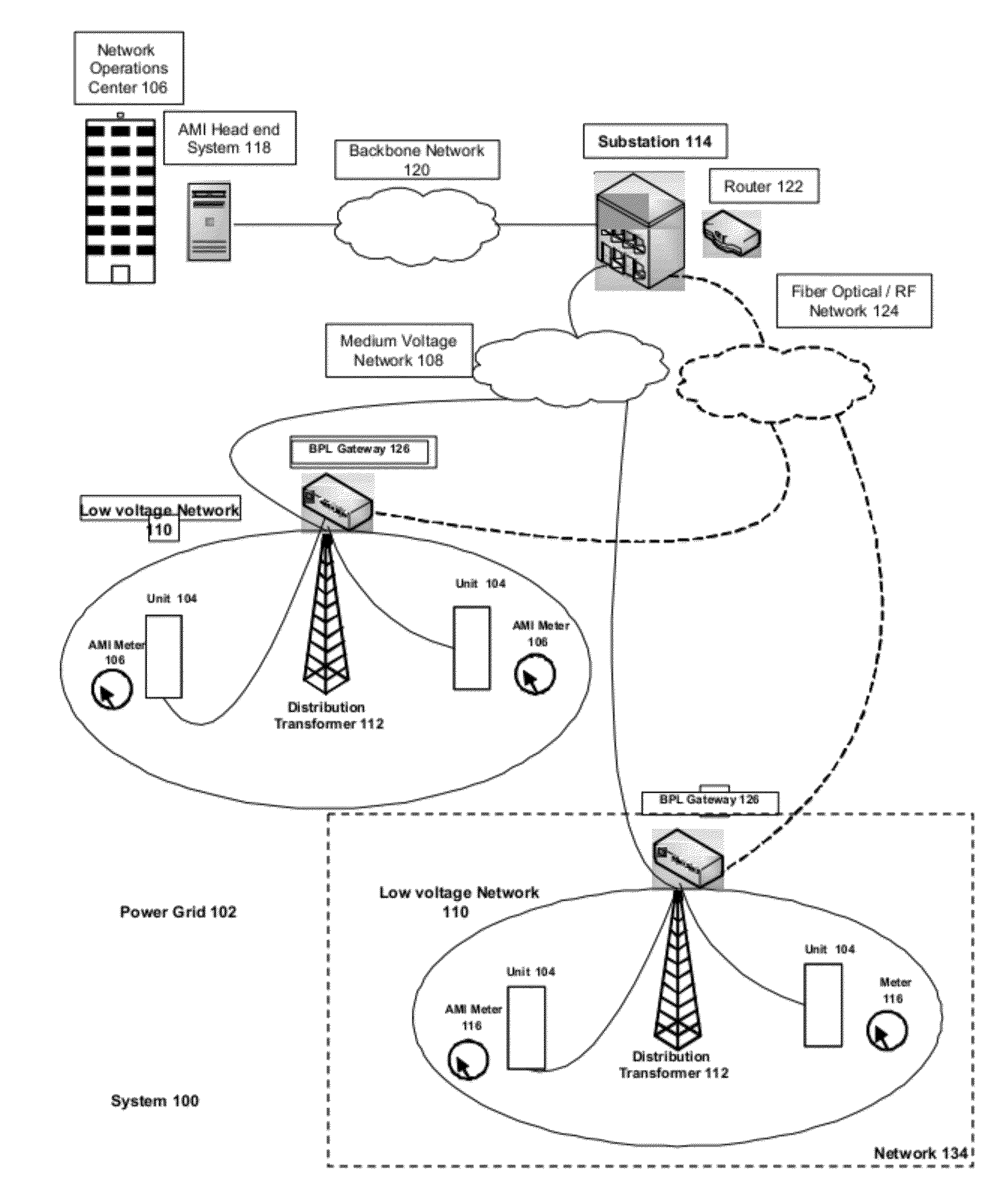
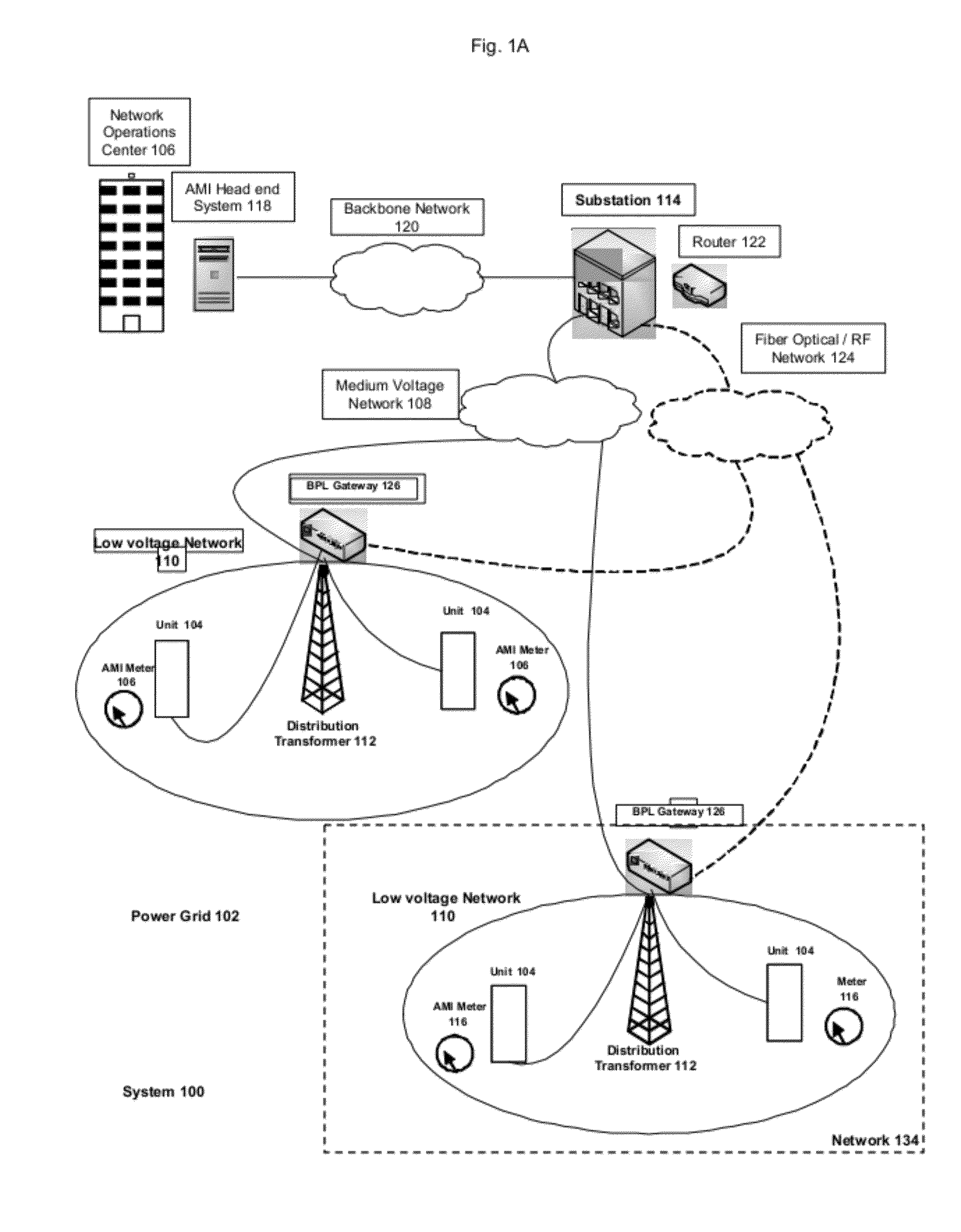
[0076]FIG. 1A illustrates one embodiment of a high speed advanced metering infrastructure (“AMI”) system 100. System 100 provides both electricity transmission and data transmission from power grid 102 to units 104. Units 104 are a physical location requiring power, such as a house, an apartment building, an office tower, a shopping mall, a factory, etc. Network operations center 106 is connected to system 100 and provides administrat...


PUM


Abstract

The disclosure relates to a meter for monitoring usage of power provided by a power transmission system to a site. The meter comprises: a meter module connected to a power feed associated with the power transmission system to provide readings relating to the power; a messaging module to provide messages to the power transmission system; a connection to an alternating current (AC) power supply; a rectifier circuit connected to the AC power supply to generate a direct current (DC) power signal; a capacitive circuit connected to an output of the rectifier circuit, the capacitive circuit including a capacitor for storing a voltage for temporarily providing replacement power for the rectifier circuit; and a switching regulator circuit connected to the output of the rectifier circuit and the capacitive circuit, the switching regulator converting the DC voltage signal to a stepped down voltage signal for the meter module.

Description

FIELD OF DISCLOSURE[0001]The disclosure described herein relates to a system and method for providing power to a power meter (such as a utility meter) connected to a powerline, such as municipal power lines providing electric power to a household.BACKGROUND[0002]Powerline networks provide energy from a power source (e.g. a hydroelectric dam) to a network of residential and commercial customer sites. The power carried over transmission lines in the network can be distributed through a series of sub-networks to the actual sites. Meters at the sites monitor the power usage, which provides usage data for billing purposes. Some meters provide automated remote transmissions of reading data to a central location, such as a head end of the power network. Such meters have limited capabilities.SUMMARY OF DISCLOSURE[0003]In a first aspect, a meter for monitoring usage of power provided by a power transmission system to a site is provided. The meter comprises: a meter module connected to a powe...

Claims


Application Information

Patent Timeline
Patent Type & Authority Applications(United States)
IPC IPC(8): G01R19/22
CPCG01D4/002H04B3/546H04B2203/5433H04L67/12Y02B90/248Y02B90/245Y04S20/30Y02B90/246Y04S20/32Y04S20/40Y04S20/42Y04S20/52G01D4/004Y02B90/241Y04S40/18G08C19/28H04B3/54Y02B90/20G01R19/0007G01R19/165G01R31/42
Inventor SOBOTKA, PETERSHI, XIAO MINGLONG, YAN
Owner CORINEX COMM CORP
Why Eureka
Try Eureka