

Magnetic position detection apparatus
a magnetic position and detection apparatus technology, applied in the direction of instruments, galvano-magnetic devices, magnetic field measurement using galvano-magnetic devices, etc., can solve the problems of increasing manufacturing costs and difficult manufacturing, and achieve the effect of reducing the variance of a signal, facilitating manufacturing, and inexpensive magnetic position detection
- Summary
- Abstract
- Description
- Claims
- Application Information
AI Technical Summary
Benefits of technology
Problems solved by technology
Method used
Image

Examples
first embodiment
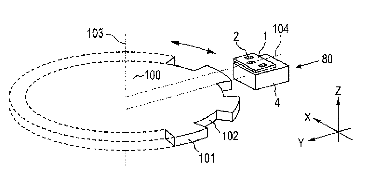
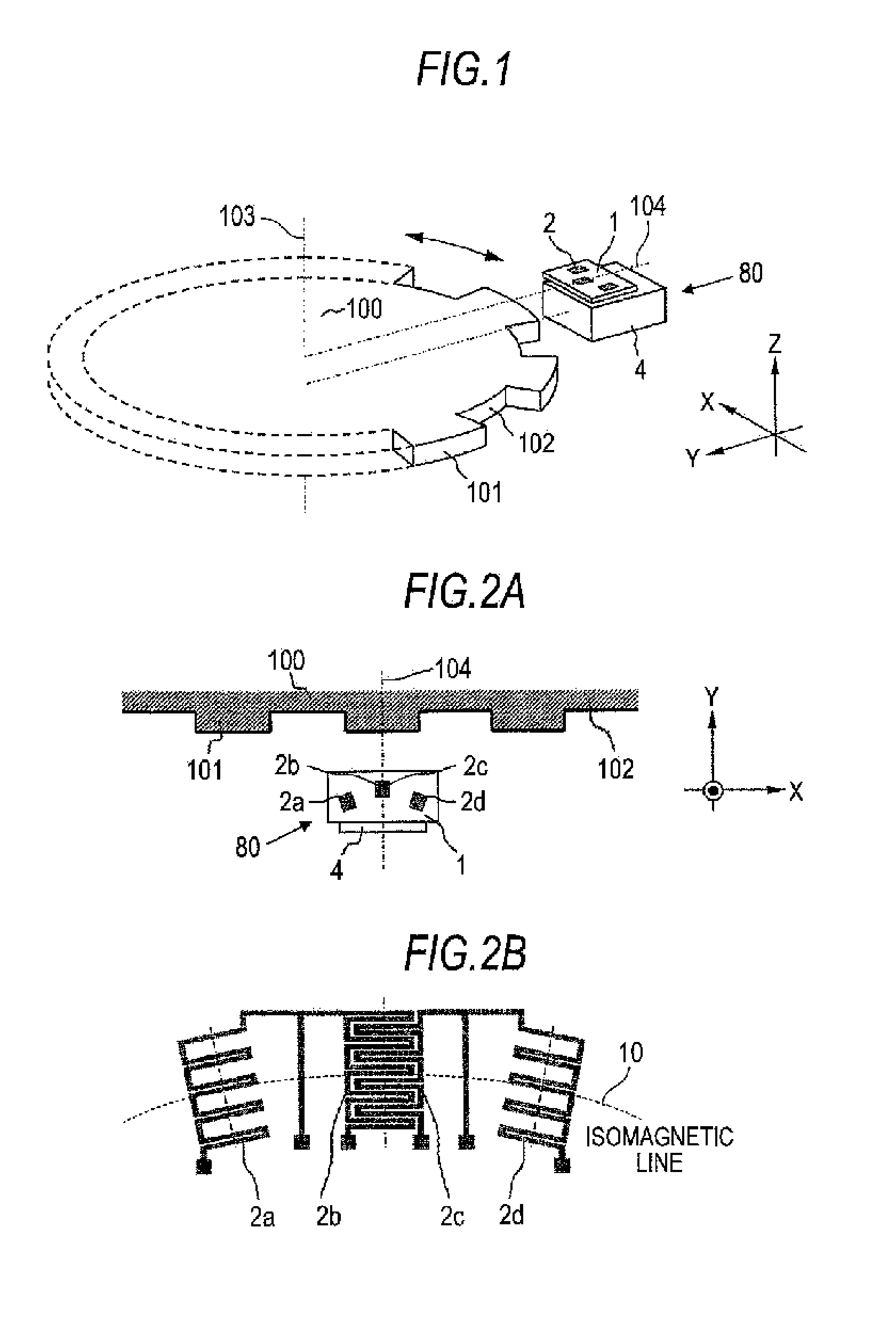
[0038]FIG. 1 shows an example where a magnetic position detection apparatus 80 according to a first embodiment of the invention is disposed relative to a magnetic mobile object 100.
[0039]The magnetic mobile object 100 is a substantially disc-shaped magnetic object rotating about a rotation axis (center axis) 103. A radially-protruding tooth portion 101 and a radially-recessed slot portion 102 are formed alternately all along the circumference of the magnetic mobile object 100.
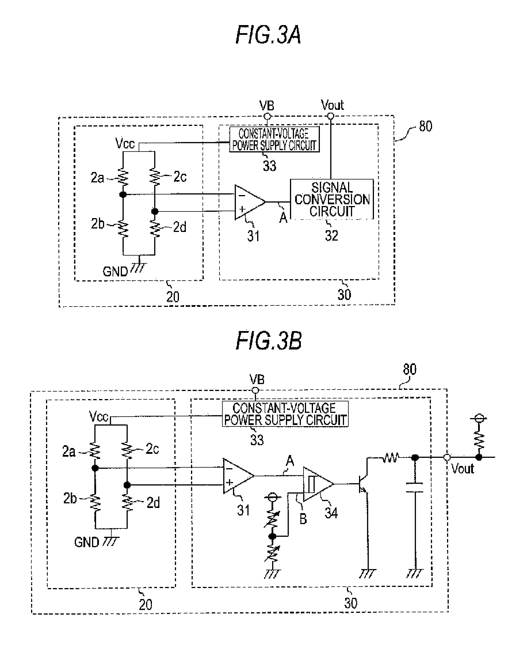
[0040]In order to detect a movement of the magnetic mobile object 100, the magnetic position detection apparatus 80 is disposed with a predetermined spacing from the magnetic mobile object 100. The magnetic position detection apparatus 80 includes a substrate 1, a bridge circuit 20 including a magneto-electric converting element 2 (see FIGS. 3A and 3B), a detection circuit 30 (see FIGS. 3A and 3B), and a magnet 4. The bridge circuit 20 has first through fourth magneto-electric converting elements 2a through 2d ...
second embodiment
[0055]A magnetic position detection apparatus 80 according to a second embodiment of the invention is an improved example of the first embodiment above and additionally includes a flux guide between a magneto-electric converting element 2 and a magnet 4.
[0056]FIGS. 8A through 8C are plan views and a side view of the magnetic position detection apparatus 80 according to the second embodiment of the invention. FIG. 8A is a plan view showing locations of a substrate 1, a magnet 4, and a flux guide 5. FIG. 8b is a plan view showing, in enlargement, locations of first through fourth magneto-electric converting elements 2a through 2d by way of example. FIG. 8C is a side view showing locations of the substrate 1, the magnet 4, and the flux guide 5 by way of example.
[0057]Referring to FIGS. 8A and 8B, a surface of the substrate 1 is substantially perpendicular to a magnetization direction of the magnet 4 and the flux guide 5 has a surface perpendicular to the magnetization direction of the ...
third embodiment
[0065]A magnetic position detection apparatus 80 according to a third embodiment of the invention includes, as with the second embodiment above, a flux guide 5 made of a magnetic material between a magneto-electric converting element 2 and a magnet 4. The flux guide 5 is, however, of a shape different from the shape of the counterpart in the second embodiment above and it is an improved example of the counterpart in the second embodiment above.
[0066]FIG. 11 is a perspective view of the magnetic position detection apparatus 80 according to the third embodiment of the invention showing a location thereof relative to a magnetic mobile object 100 by way of example.
[0067]FIG. 12 is a side view showing locations a substrate 1, a magnet 4, and a flux guide 5 of the magnetic position detection apparatus 80 according to the third embodiment of the invention by way of example.
[0068]As are shown in FIG. 11 and FIG. 12, a surface of the substrate 1 is substantially perpendicular to a magnetizat...
PUM
 Abstract
Description
Claims
Application Information