Timing skew error correction apparatus and methods

a technology of analog-to-digital converter and time skew error correction, which is applied in the direction of pulse automatic control, electric analogue stores, instruments, etc., can solve the problems of imperfect common-mode rejection (cmr), affecting the integrity of the held signal, and difficulty in perfectly matching the input impedance of the two t/h circuit inputs

Active Publication Date: 2012-05-24
TEXAS INSTR INC
View PDF8 Cites 17 Cited by
  • Summary
  • Abstract
  • Description
  • Claims
  • Application Information

AI Technical Summary

Benefits of technology

[0015]Embodiments herein operate to compensate for timing skew between inverse phases (e.g., differential phases) of an analog signal appearing at the input to an analog capture circuit such as a track-and-hold or sample-and-hold circuit associated with an ADC or similar device. Each of two capture clocks is used to capture one of the phases. One or more delay circuits are configured to create a differential delay between clock transitions associated with the two capture clocks. The differential delay is proportional to the skew, if any, between the inverse phases. As a result, the phases are effectively sampled at substantially identical points on a phase axis associated with the two phases. This process is referred to hereinafter as “phase sampling alignment.” Embodiments operate to sample-align the two phases and to thereby decrease a common-mode signal component resulting from the phase misalignment condition.

Problems solved by technology

In the latter case, it is difficult to perfectly match the input impedances of the two T / H circuits.
A difference in the input impedances results in imperfect common-mode rejection (CMR).
The common-mode component may negatively impact the integrity of the held signal, leading to non-linearity and distortion.
Consequently, the problem of decreased CMR resulting from independent T / H inputs may be particularly acute for certain high sampling rate, high frequency applications requiring high levels of linearity.
The delay skew results from path-length differences associated with the separate T / H circuits and associated circuit paths.
Higher frequency and / or greater skew result in an increase in common-mode amplitude, a decrease in the apparent amplitude of the differential signal, and a loss of signal-to-noise ratio (SNR).

Method used


Image

  • Timing skew error correction apparatus and methods
  • Timing skew error correction apparatus and methods
  • Timing skew error correction apparatus and methods

Examples


Embodiment Construction

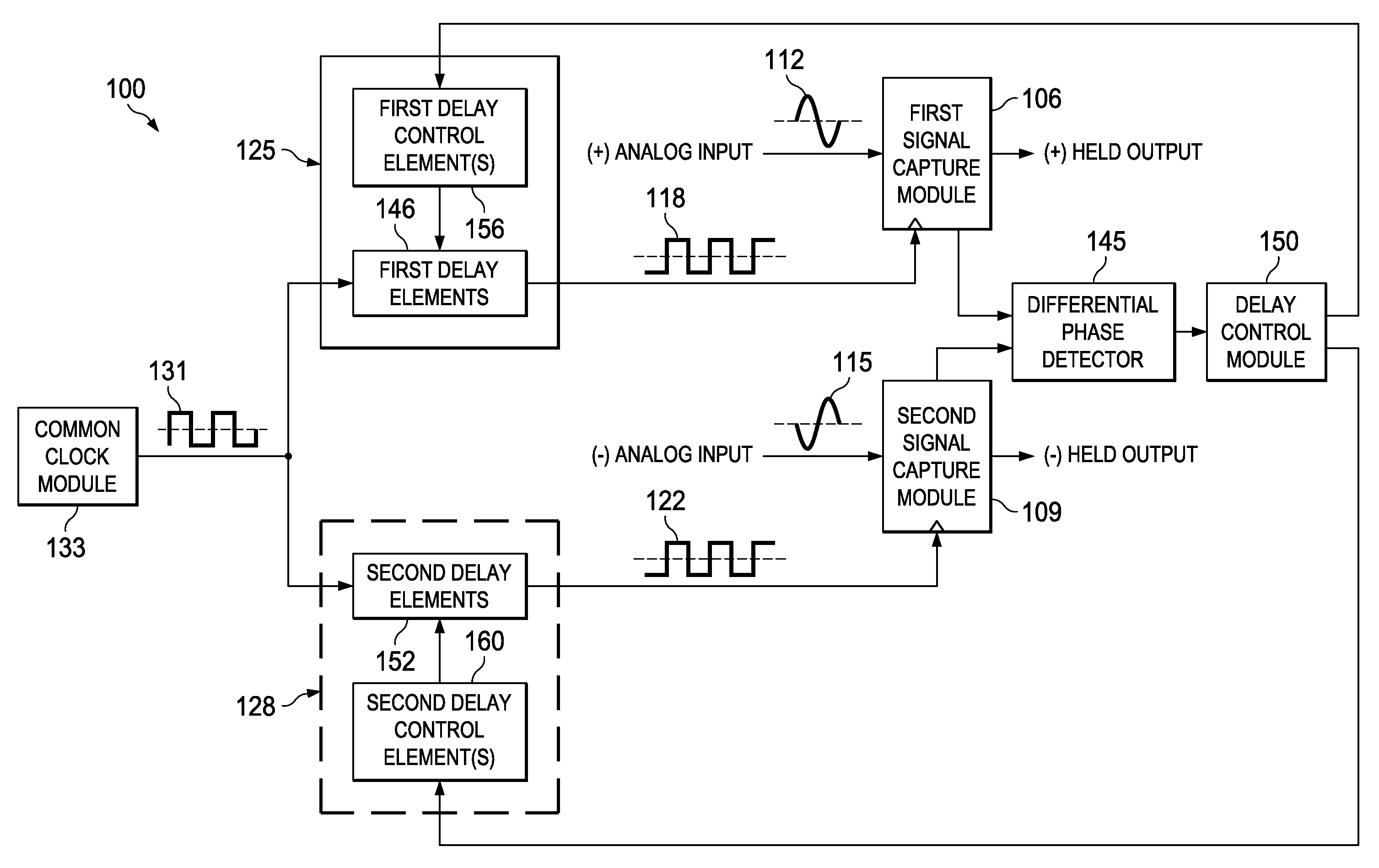
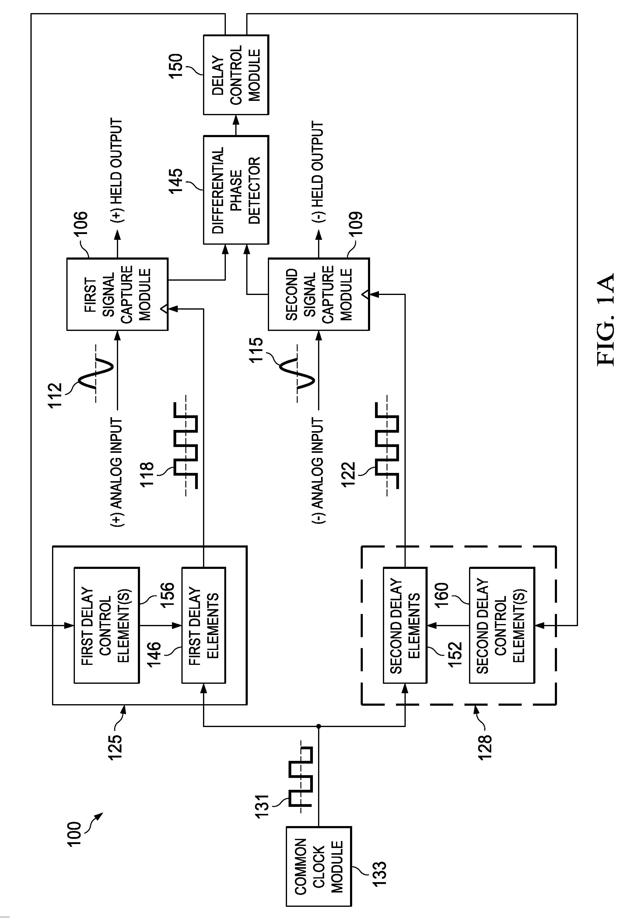
[0016]FIG. 1A is a block diagram of a dual-clocked analog signal sampling circuit 100 according to various example embodiments of the current invention. The sampling circuit 100 includes first and second signal capture modules 106 and 109. In some embodiments, the first and second signal capture modules 106 and 109 comprise track-and-hold circuits, sample-and-hold circuits, or both. Although example embodiments may be described in the context of track-and-hold circuits associated with ADC architectures, contemplated embodiments may apply to other types of circuits and applications.

[0017]The first and second signal capture modules 106 and 109 operate to sample a first phase 112 and a second phase 115, respectively, of an analog input signal. The first and second phases 112 and 115 may be inverse phases (e.g., differential phases). The first phase 112 is sampled by capturing the magnitude of the first phase 112 at the first signal capture module 106 upon receipt of a clock transition ...


PUM


Abstract

Apparatus and methods disclosed herein operate to compensate for skew between inverse phases (e.g., differential phases) of an analog signal appearing at the inputs of an analog signal capture circuit such as a track-and-hold or sample-and-hold circuit associated with an ADC or similar device. Each of two capture clocks is used to capture one of the inverse phases. One or more delay circuits are configured to create a differential delay between clock transitions associated with the two capture clocks. The differential delay is proportional to the input skew between the inverse phases. The phases are consequently sampled at substantially identical points on a phase domain axis. Embodiments operate to create phase sampling synchronicity and to thereby decrease the amplitude of a common-mode signal component that results from the skew. Increased linearity and decreased distortion may result.

Description

TECHNICAL FIELD[0001]Embodiments described herein relate to apparatus and methods associated with analog-to-digital converters, including structures and techniques related to analog input timing skew error correction.BACKGROUND INFORMATION[0002]Analog-to-digital converters (ADCs) typically include one or more sample-and-hold or track-and-hold (T / H) input circuits. The term T / H shall hereinafter refer to either or both sample-and-hold or T / H circuits. A T / H input stage captures the magnitude of an analog signal at a sample time and maintains the sampled amplitude for subsequent quantization and processing.[0003]Some ADCs, including ADCs with fully differential and / or pseudo-differential inputs, may utilize two T / H circuits to capture an analog signal. One T / H circuit captures a (+) phase of the signal and a second, independent T / H circuit captures the (−) phase of the signal.[0004]In the latter case, it is difficult to perfectly match the input impedances of the two T / H circuits. One...

Claims


Application Information

Patent Timeline
Patent Type & Authority Applications(United States)
IPC IPC(8): H03L7/00
CPCH03L7/0812H03M1/0624G11C27/02H03M1/1245H03M1/0836
Inventor PAYNE, ROBERT FLOYDPRATT, PHILIP M.SMITH, WILLIAM DAVID
Owner TEXAS INSTR INC
Why Eureka
Try Eureka