
Telescopic probe monitoring system for riverbedelevation monitoring at bridge piers

Inactive Publication Date: 2012-05-24
NAT APPLIED RES LAB
View PDF1 Cites 5 Cited by
  • Summary
  • Abstract
  • Description
  • Claims
  • Application Information

AI Technical Summary

Benefits of technology

[0019]It is a further object of the present invention to provide a telescopic probe monitoring system for riverbed elevation monitoring at bridge piers, which is disposed above the riverbed. There is no need to dig in the riverbed for mounting the telescopic probe monitoring system. Thus the set-up of the system is simple and the cost is reduced.
[0020]It is a further object of the present invention to provide a telescopic probe monitoring system for riverbed elevation monitoring at bridge piers, which obtains data of the riverbed elevation in real-time manner and sends the data of the riverbed elevation to the remote monitor unit for real-time monitoring and recording the riverbed elevation changes. There is no need to transmit monitoring images. Thus the data amount transmitted is reduced and the bandwidth consumption is reduced effectively.
[0022]Moreover, the control module can also get the distance of the multi-layer tube's extension according to the movement and status of the measurement module. The riverbed elevation is transmitted to the remote monitor unit in a real-time manner for real-time monitoring of the riverbed elevation. The telescopic probe monitoring system for riverbed elevation monitoring is waterproof and is able to be disposed over the riverbed under the water, without being embedded into the riverbed. Thus there is no need to dig out the riverbed for mounting the monitoring system. Therefore, the simple set-up of the monitoring system saves both labor and cost.

Problems solved by technology

In recent years, natural disasters caused by storms and associated floods become more frequent and severe all over the world.
When the typhoon or hurricane comes, it causes serious flooding in the rivers and severe scour around the bridge pier leading to the exposure of bridge foundations.
As a result, the lateral load acted on the bridge pier is insufficient and the bridge may be tilted or broken.
Once the flooding is too violent, the pier may even be washed away, and the bridge collapses and people passing through the bridge may fall into the river.
The above situation not only results in traffic interruption, but also great damages to human lives, common property and local construction.
The disadvantage of the method is that it requires digging in the riverbed for mounting the brick array and each set of array can be used only once.
Moreover, only the scour depth is learned while the sediment deposition is unable to detect.
The disadvantage of this method is that it only records the scour depth but the sediment deposition is unable to be detected.
The disadvantage of this method is the large power consumption.
Moreover, the transmission quality is unstable, easy to be interfered by the motor due to the wireless data transmission.
Under harsh environments, the interface between the water and the sand surface may be difficult to judge.
However, the interface between sand and water is still difficult to be defined under harsh environments.
Moreover, this method needs to embed the device into the riverbed.
When sediments deposit, it is unable to detect.
The disadvantage of the method is that this method is only applied to detect scouring of the sand surface.
As to the sediment being deposited on the riverbed, it just doesn't work.
The disadvantage of the method is that the optical fiber requires contacting the water surface or sand surface.
The optical fiber is fragile and is easy to get damaged.
The disadvantage of this method is that the length of the measuring rod should be quite long if the water surface is much higher than the sand surface.
Moreover, the device is easy to be destroyed by external objects such as flooding or rocks.
Thus how to monitor the riverbed scouring at bridge piers by a better method for extending the lifetime of the bridge has become an important issue now.

Method used


Image

  • Telescopic probe monitoring system for riverbedelevation monitoring at bridge piers
  • Telescopic probe monitoring system for riverbedelevation monitoring at bridge piers
  • Telescopic probe monitoring system for riverbedelevation monitoring at bridge piers

Examples


Embodiment Construction

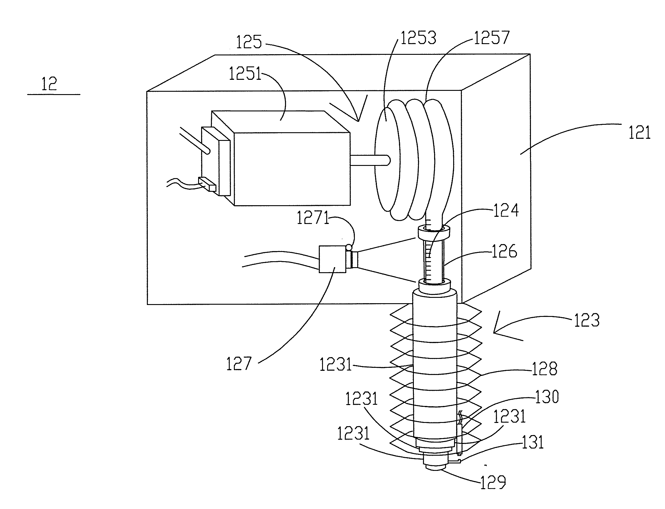
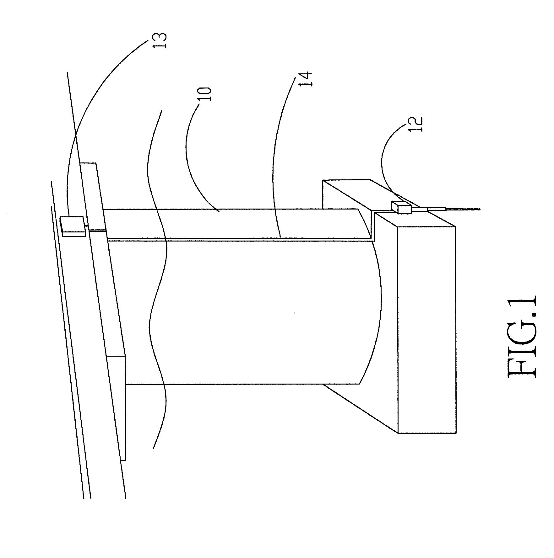
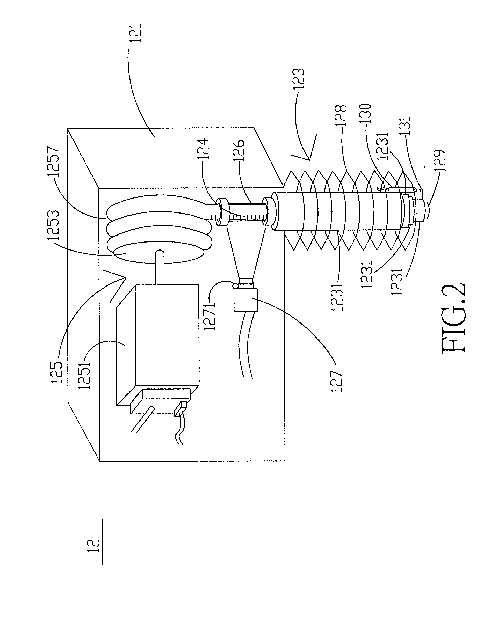
[0029]Referring to FIG. 1, a schematic drawing of an embodiment of a telescopic probe monitoring system for riverbed elevation monitoring at bridge piers is revealed. As shown in the figure, the telescopic probe monitoring system is arranged at a pier 10 and is used for real-time monitoring riverbed elevation changes under the water. The disposition way of the telescopic probe monitoring system over the pier 10 is not limited and the position of the telescopic probe monitoring system can be above or under the water. The telescopic probe monitoring system of the present invention includes a measurement module 12 and a control module 13. The measurement module 12 is to detect the riverbed under the water and send data measured to the control module 13 for calculation and image recognition by a signal transmission line 14. The control module 13 is connected to a power supply unit 15 (as shown in FIG. 3) that provides both the measurement module 12 and the control module 13 power requir...


PUM


Abstract

A telescopic probe monitoring system for riverbed elevation monitoring at a bridge pier is revealed. The system includes a measurement module for measuring riverbed elevation under water and a control module. The measurement module includes a housing, a multi-layer tube, a driving member with scales, a photographic unit for capturing images, and a sensing unit. The control module controls the driving member to extend the multi-layer tube. Thus the sensing unit on the bottom of the multi-layer tube contacts the riverbed and then sends a sensing signal to the control module for stopping pushing the multi-layer tube and controlling the photographic unit to capture images of the driving member. According to the images and movement of the measurement module, the control module learns the riverbed elevation and sends the riverbed elevation to a remote monitor unit for real-time monitoring of the riverbed elevation.

Description

BACKGROUND OF THE INVENTION[0001]1. Fields of the invention[0002]The present invention relates to a monitoring system for riverbed elevation monitoring at bridge piers, especially to a telescopic probe monitoring system for riverbed elevation monitoring at bridge piers in real time manner.[0003]2. Descriptions of Related Art[0004]In recent years, natural disasters caused by storms and associated floods become more frequent and severe all over the world. When the typhoon or hurricane comes, it causes serious flooding in the rivers and severe scour around the bridge pier leading to the exposure of bridge foundations. As a result, the lateral load acted on the bridge pier is insufficient and the bridge may be tilted or broken. Once the flooding is too violent, the pier may even be washed away, and the bridge collapses and people passing through the bridge may fall into the river. The above situation not only results in traffic interruption, but also great damages to human lives, common...

Claims


Application Information

Patent Timeline
IPC IPC(8): H04N7/18
CPCH04N7/183Y02A20/402
Inventor YU, TENG-YICHANG, WEN-YILIN, FRANCOLEE, LUNG-CHANGTSAI, WHEY-FONELAI, JIHN-SUNGLOH, CHIN-HSIUNG
Owner NAT APPLIED RES LAB
Learn More