Pressure application apparatus and pressure application method
a technology of pressure application apparatus and pressure application method, which is applied in the direction of instruments, sustainable manufacturing/processing, and semiconductor/solid-state device details, etc., can solve the problems of positional shift and inability to tolerate positional shift, and achieve the effect of greater accuracy
- Summary
- Abstract
- Description
- Claims
- Application Information
AI Technical Summary
Benefits of technology
Problems solved by technology
Method used
Image
Examples
first embodiment
1. First Embodiment
[0058]1-1. Apparatus Structure
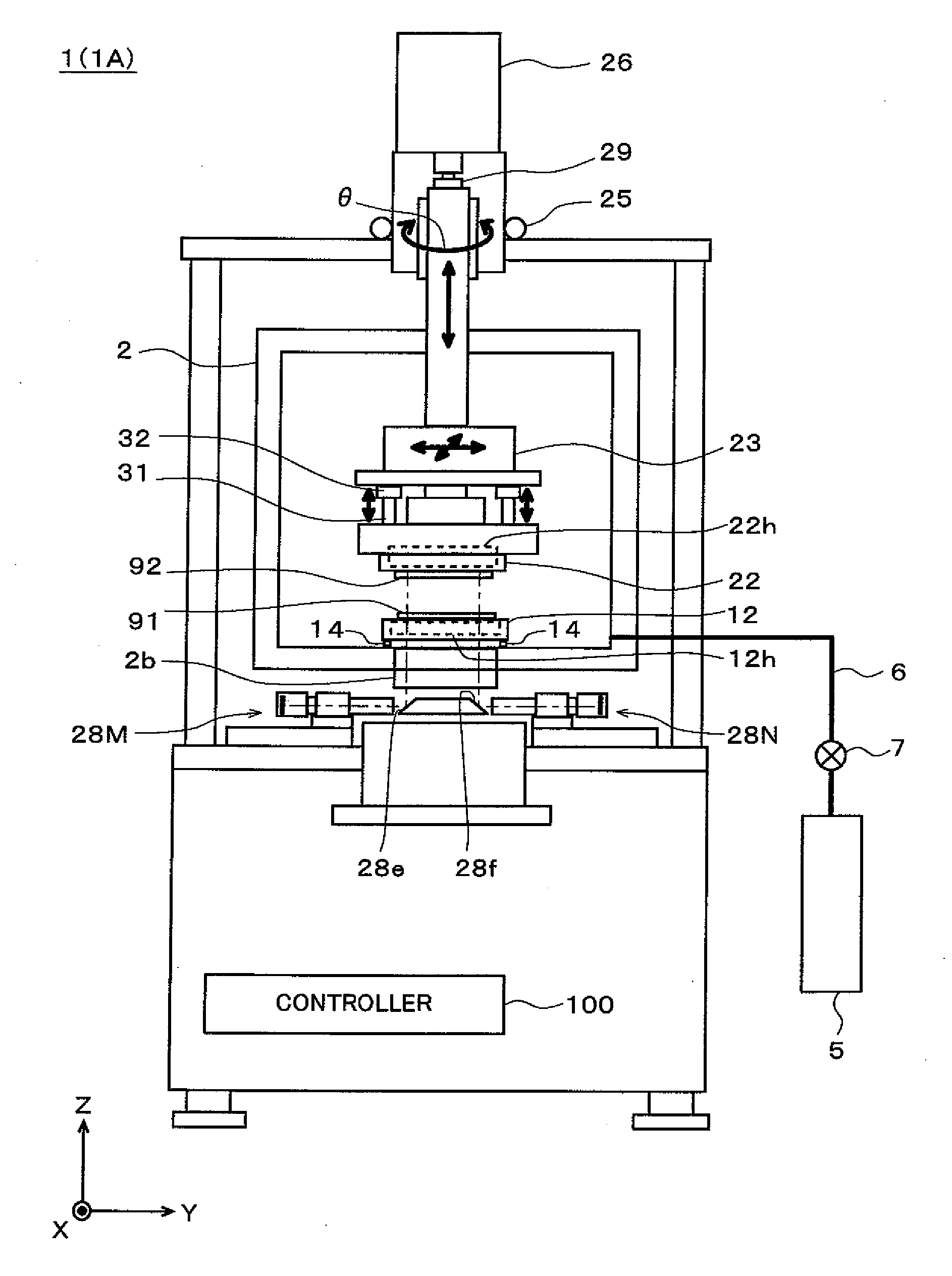
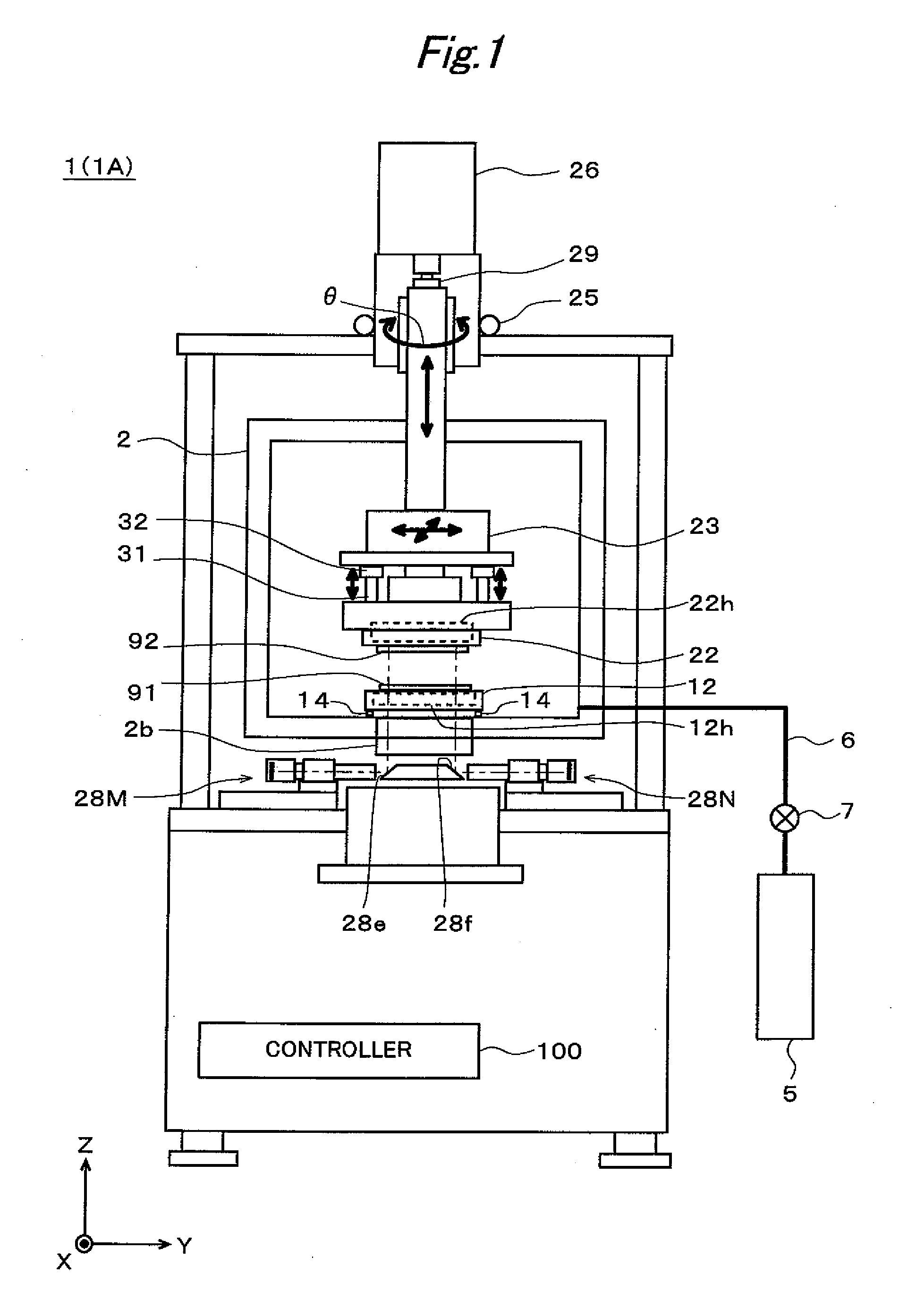
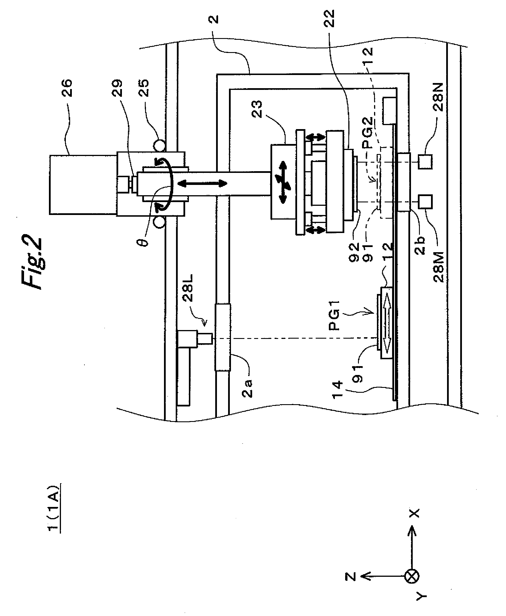
[0059]FIGS. 1 and 2 are side views showing the internal structure of a bonding apparatus 1 (also referred to as “1A”) according to a first embodiment of the present invention. Note that, for the sake of convenience, directions and the like are shown using an XYZ orthogonal coordinate system in the following figures.
[0060]The bonding apparatus 1 is an apparatus for bonding an object to be bonded 91 and an object to be bonded 92 together by disposing the objects to be bonded 91 and 92 facing each other and applying pressure and heat thereto in a chamber (vacuum chamber) 2 under reduced pressure. Here a situation is assumed in which a substrate 91 and a chip (component) 92 are bonded together, more specifically, a situation in which pads (electrodes) 93 on the substrate 91 and metal bumps (electrodes) 94 on the chip 92 are bonded together, as shown in FIGS. 9 and 10. So-called solder bumps formed of an appropriate solder material can be ...
second embodiment
2. Second Embodiment
[0129]A second embodiment is a variation of the first embodiment. The following description focuses on differences from the first embodiment.
[0130]In the second embodiment, a case is illustrated in which an operation of adjusting parallelism is also performed in accordance with the post-contact measurement of a positional shift.
[0131]As mentioned above, there are cases where the stage 12 and the head 22 are disposed at an angle to each other, and by extension, the objects to be bonded 91 and 92 are disposed at an angle to each other (not in parallel with each other) as shown in FIG. 10, because the parallelism of the stage 12 and the head 22 is not enough. A shift or the like in the contact state may increase due to such an angled disposition.
[0132]In view of this, in the second embodiment, the parallelism adjustment operation is also executed in accordance with the post-contact positional shift measurement. Specifically, as shown in FIG. 18, the parallelism adju...
third embodiment
3. Third Embodiment
[0146]In the first embodiment, the case is illustrated in which the objects to be bonded 91 and 92 are temporarily brought out of contact with each other by temporarily elevating the object to be bonded 92 in order to eliminate a post-contact positional shift, but the present invention is not limited thereto. For example, the positioning of the objects to be bonded 91 and 92 may be performed by correcting a positional shift between the objects to be bonded 91 and 92 while maintaining the contact state of the objects to be bonded 91 and 92. The description of a third embodiment gives such a variation, focusing on differences from the first embodiment.
[0147]FIG. 23 is a flowchart showing an operation according to the third embodiment. As shown in FIG. 23, in the present embodiment, if it is determined that there is a positional shift of a predetermined amount or more (step S15), the procedure proceeds directly to step S27, without involving the contact release opera...
PUM
 Abstract
Description
Claims
Application Information
 - R&D
- Intellectual Property
- Life Sciences
- Materials
- Tech Scout
- Unparalleled Data Quality
- Higher Quality Content
- 60% Fewer Hallucinations
Browse by: Latest US Patents, China's latest patents, Technical Efficacy Thesaurus, Application Domain, Technology Topic, Popular Technical Reports.
© 2025 PatSnap. All rights reserved.Legal|Privacy policy|Modern Slavery Act Transparency Statement|Sitemap|About US| Contact US: help@patsnap.com


