Llc converter active snubber circuit and method of operation thereof

a technology of active snubber circuit and power converter, which is applied in the direction of electric variable regulation, process and machine control, instruments, etc., can solve the problems of power converters being more lossy and less efficient, and generating high frequency oscillations

Active Publication Date: 2012-05-24
ABB POWER ELECTRONICS INC
View PDF0 Cites 30 Cited by
  • Summary
  • Abstract
  • Description
  • Claims
  • Application Information

AI Technical Summary

Benefits of technology

[0006]One aspect provides an active snubber circuit for a power converter. In one embodiment, the circuit includes: (1) a series-coupled first capacitor and diode associated with a secondary-side switch in the power converter and coupled to an output thereof and (2) an active snubber circuit switch coupled in parallel with the diode and configured to receive a control signal that closes the active snubber circuit switch during at least a portion of a time during which the secondary-side switch is open.

Problems solved by technology

The residual parasitic elements mentioned above, however, may generate high frequency oscillations that appear as undesired “ringing” waveforms in the power converter associated with the switching transitions, particularly, those associated with the transformer and switches.
Additionally, the deleterious ringing waveforms cause the power converter to be more lossy and less efficient.
Some of the loss manifests itself as undesirable electromagnetic interference (EMI) causing regulatory problems which must be addressed.
Due to the relatively small resistance values inherent in the transformer and inductor elements, the ringing energy may only be lightly damped in the power converter.

Method used


Image

  • Llc converter active snubber circuit and method of operation thereof
  • Llc converter active snubber circuit and method of operation thereof
  • Llc converter active snubber circuit and method of operation thereof

Examples


Embodiment Construction

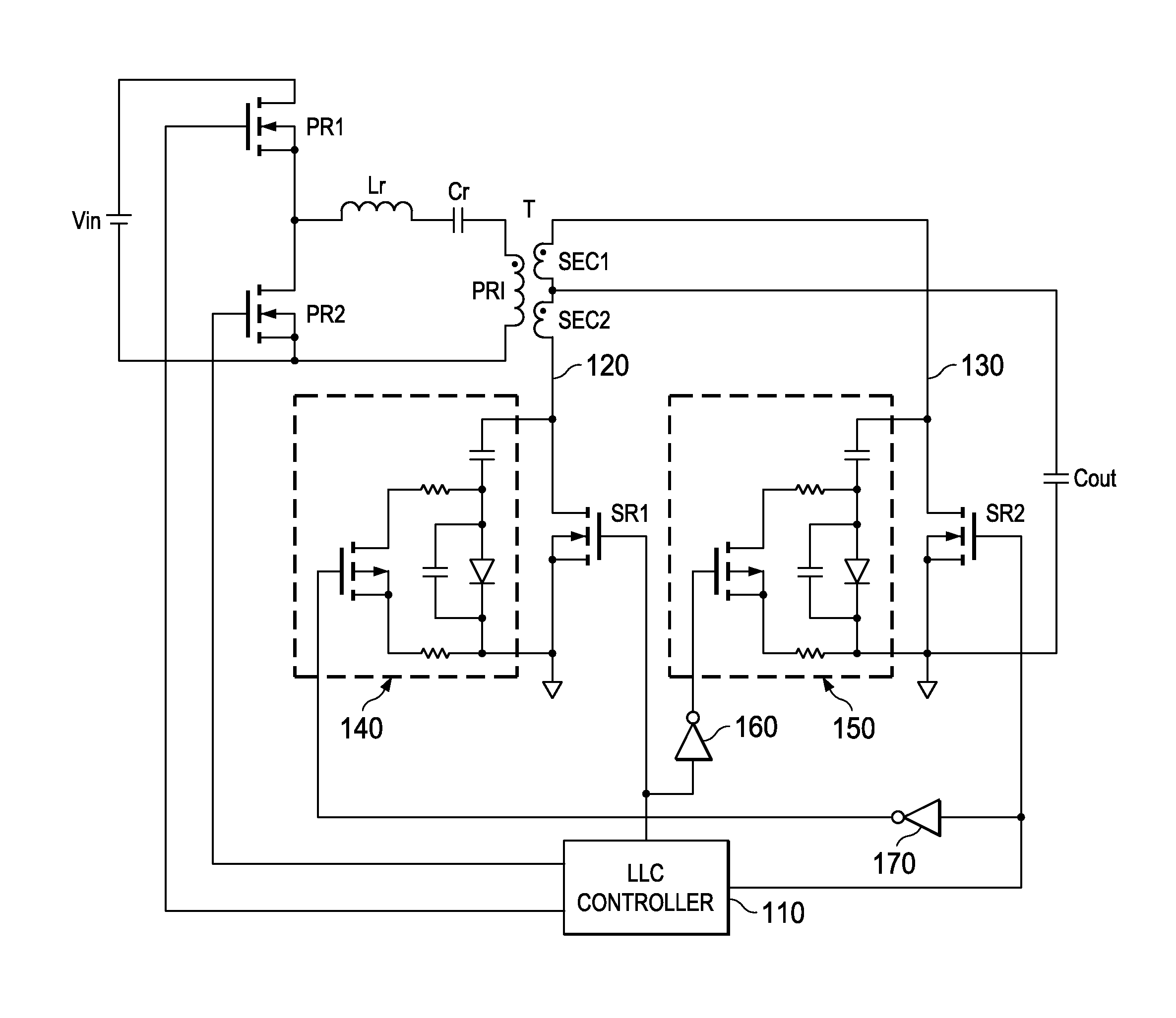
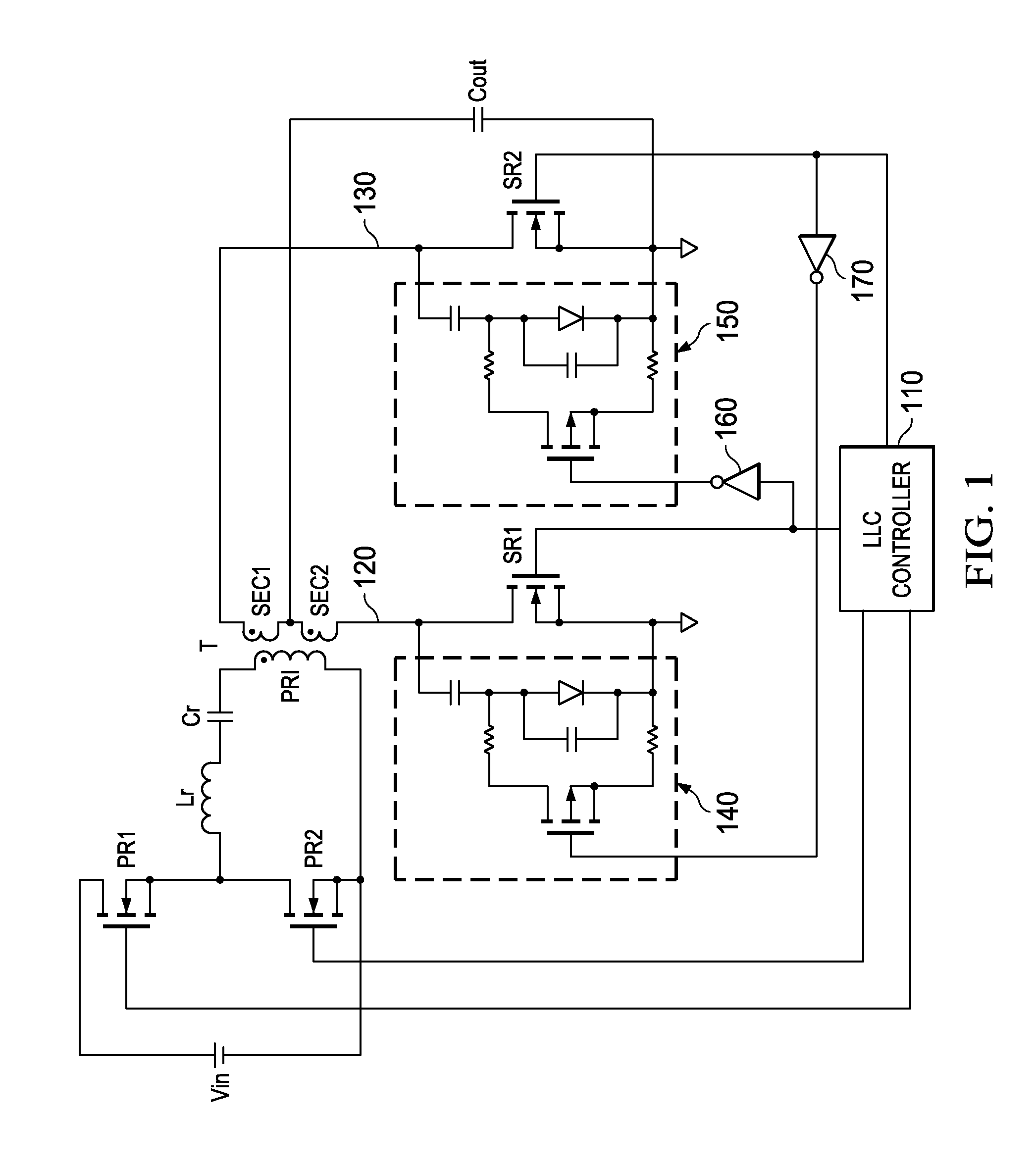
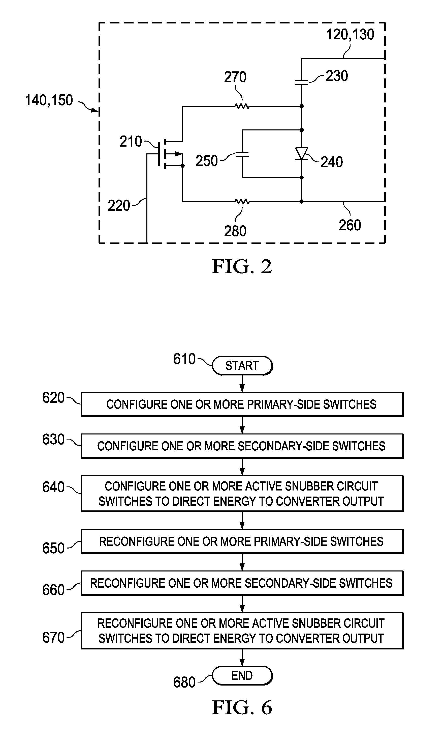
[0016]As stated above, residual parasitic elements in power converters may generate high frequency oscillations that appear as undesired ringing waveforms during switching transitions. What is generally needed in the art is a snubber circuit capable of reducing the undesirable ringing waveforms occurring in the rectifier during switching transitions thereof without significantly reducing the converter's efficiency. Such a snubber circuit may allow lower-rated components to be employed in the converter or increase the reliability of the components employed therein. Previous snubber circuits for an LLC converter are typically made of passive components (e.g., resistors, capacitors and diodes) that dissipate the ringing energy predominantly as heat. What is further needed in the art is an active snubber circuit that transfers the energy that would otherwise cause ringing to the output of a converter, thus employing that energy to increase the converter's efficiency. Introduced herein a...


PUM


Abstract

An active snubber circuit for a power converter, a method of operating the same and an inductor inductor capacitor converter incorporating the circuit or the method. In one embodiment, the circuit includes: (1) a series-coupled first capacitor and diode associated with a secondary-side switch in the power converter and coupled to an output thereof and (2) an active snubber circuit switch coupled in parallel with the diode and configured to receive a control signal that closes the active snubber circuit switch during at least a portion of a time during which the secondary-side switch is open.

Description

TECHNICAL FIELD[0001]This application is directed, in general, to power converters and, more specifically, to an LLC converter active snubber circuit and method of operation thereof.BACKGROUND[0002]A power converter is a power processing circuit that converts an input voltage waveform into a specified output voltage waveform. In many applications requiring a DC output, switched-mode DC / DC power converters are frequently employed to advantage. The switched-mode DC / DC power converters generally include an inverter, an isolation transformer and a rectifier on a secondary side of the isolation transformer. The inverter generally includes a main power switch, such as a field effect transistor (“FET”), that converts the DC input voltage to an AC voltage. The isolation transformer, then, transforms the AC voltage to another value and the rectifier generates the desired DC voltage at the output of the power converter. Conventionally, the rectifier includes a plurality of rectifier switches ...

Claims


Application Information

Patent Timeline
Patent Type & Authority Applications(United States)
IPC IPC(8): H02M3/335
CPCH02M3/33592H02M2001/342Y02B70/1491Y02B70/1475Y02B70/1433H02M1/342Y02B70/10
Inventor REDDY, RAGHOTHAMA
Owner ABB POWER ELECTRONICS INC
Why Eureka
Try Eureka