PMD-insensitive method of chromatic dispersion estimation for a coherent receiver

a chromatic dispersion estimation and coherent receiver technology, applied in electromagnetic transmission, electrical equipment, transmission, etc., can solve the problems of optical communication system performance, undesirable temporal spreading of optical signals, and pmd cannot be easily determined or compensated in a conventional optical communication system

Active Publication Date: 2012-05-24
INFINERA CORP
View PDF3 Cites 31 Cited by
  • Summary
  • Abstract
  • Description
  • Claims
  • Application Information

AI Technical Summary

Problems solved by technology

Some important linear impairments that can affect the performance of optical communication systems include two forms of signal distortion resulting from chromatic dispersion (CD) and polarization mode dispersion (PMD) of the optical signal.
Chromatic dispersion is a result of the different spectral components propagating at different speeds along the fiber, resulting in an undesirable temporal spreading of the optical signal.
PMD occurs due to the different polarization modes of the optical signal propagating along the fiber at different speeds and is affected by environmental effects and asymmetries in the optical fiber, which are often random, unpredictable and can vary over time.
Due to the random and unpredictable nature of PMD, PMD cannot be easily determined or compensated for in a conventional optical communication system.
In practice, however, implementing such DCFs and other known dispersion compensating techniques and components in the optical communication system undesirably increases the size of the system, and can be cumbersome and expensive.
Additionally, such dispersion compensation components can undesirably limit the power and spectral efficiency of the optical communication system.
One challenge, however, is that this type of coherent optical receiver should be designed to compensate for a large chromatic dispersion, such as values as high as 51,000 ps / nm.
Another challenge is that since the received signal is affected by both chromatic dispersion and PMD, it is more difficult to estimate the effects of either one.
In a system with potentially large chromatic dispersion and PMD, it is very difficult to accurately and efficiently estimate these effects in the receiver, thus seriously degrading performance of the optical communication system.
These solutions, however, are limited in that in many systems, especially switched systems in which the signal may travel via one of several different links, the chromatic dispersion effects cannot be easily known or determined in advance because each link scenario has a different chromatic dispersion, or the adaptive filter cannot be easily or efficiently updated.
For each iteration, the step of calculating the chromatic dispersion coefficients results in even greater complexity.
Additionally, there is added delay in such systems due to the time required for the acquired signal to be allocated for the chromatic dispersion scanning steps discussed above.
Another disadvantage of such methods is that the chromatic dispersion cannot accurately be estimated until the clock recovery loop is locked, but the clock recovery loop cannot lock without the chromatic dispersion value first being determined, leading to added delay in acquiring a desired sensitivity of the clock recovery loop.
Such methods of scanning for the chromatic dispersion value lead to an undesired increase in processing time and undue complexity in the receiver.
These methods, however, are still too inefficient for a receiver when there is large chromatic dispersion in the optical communication system.
Furthermore, for optical communication systems with large PMD, the above receiver techniques do not provide satisfactory sensitivity with respect to the PMD effects, thus resulting in poor system performance.
Specifically, the chromatic dispersion estimation methods discussed above fail to discriminate between actual chromatic dispersion effects and the effects of the second and higher order components of PMD present in the optical communication system.
If the estimated chromatic dispersion in these known methods includes the effects of second order PMD, the receiver sensitivity can be seriously corrupted.

Method used


Image

  • PMD-insensitive method of chromatic dispersion estimation for a coherent receiver
  • PMD-insensitive method of chromatic dispersion estimation for a coherent receiver
  • PMD-insensitive method of chromatic dispersion estimation for a coherent receiver

Examples


first embodiment

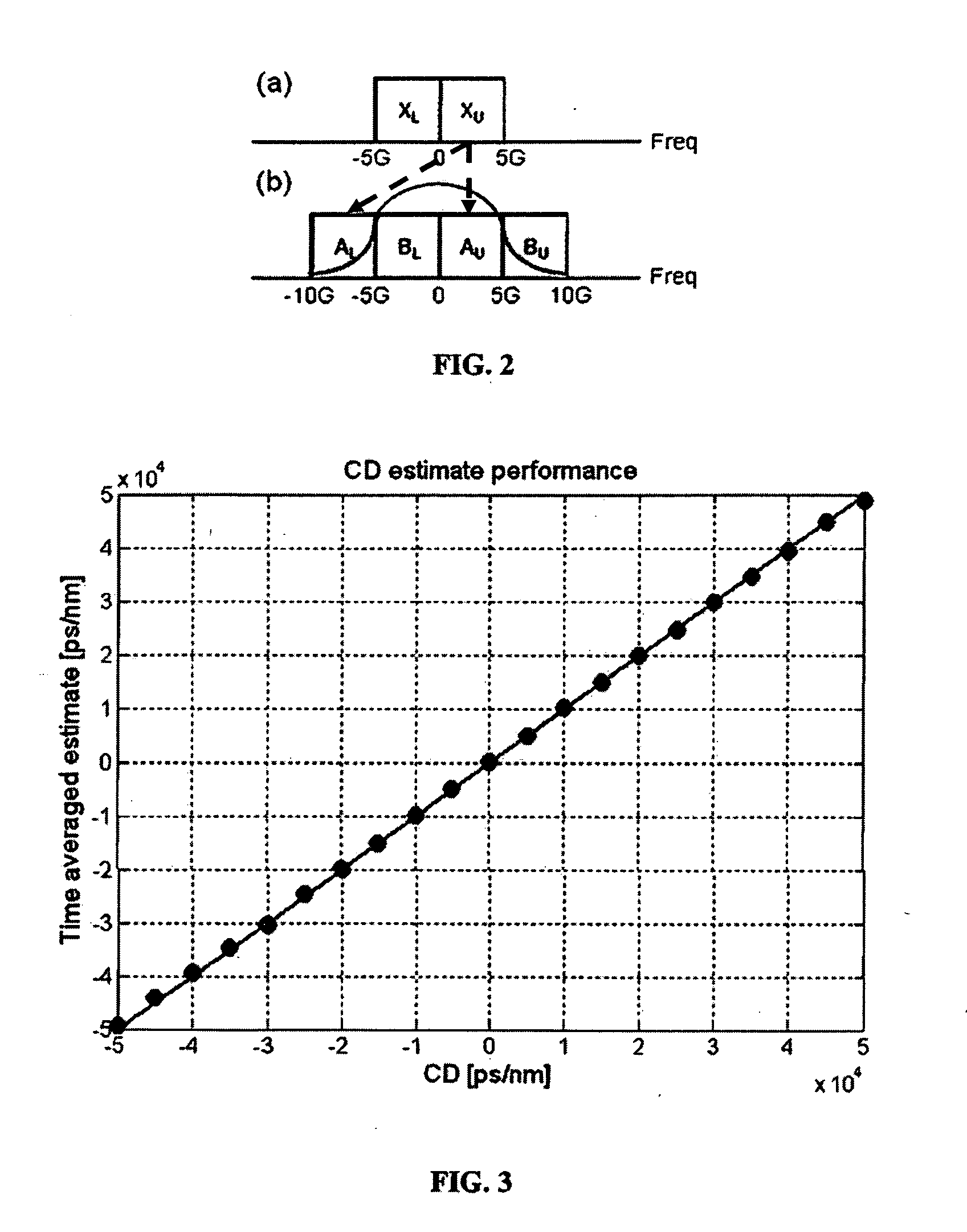
[0028]To demonstrate that exemplary methods of estimating chromatic dispersion according to the present disclosure are insensitive to PMD, estimating chromatic dispersion in an optical receiver will be explained with respect to FIG. 2. According to this first exemplary embodiment, a singularly polarized transmitted optical signal is processed in the receiver, as discussed above. A sample 10 Gbaud data spectrum of the singularly polarized transmitted signal is shown in FIG. 2(a). XU represents the random data spectrum in the upper side band of the X polarized transmitted signal, and XL represents the random data spectrum in the lower side band of the X polarized signal. To compensate for the chromatic dispersion in the optical communication system through which the polarized optical signal was transmitted, the exemplary method determines a phase difference between related frequency domain data of the received signal as a function of frequency. As discussed further below, the frequenc...

second embodiment

[0036]For example, if averaging the dot product of Eqn. 3 for 64 clock cycles, results in a 2 p rotation of the phase in each of the frequency components of Eqn. 3 with a 200 ppm clock offset, then the averaging in Eqn. 3 does not yield any useful information. Therefore, with a 200 ppm clock offset, the number of clock cycles used in the averaging step should be reduced to say 16 or less. In turn, the smaller the amount of clock offset, the greater the number of clock cycles can be used during the time-averaging step. This concept is discussed in greater detail with respect to the second embodiment below.

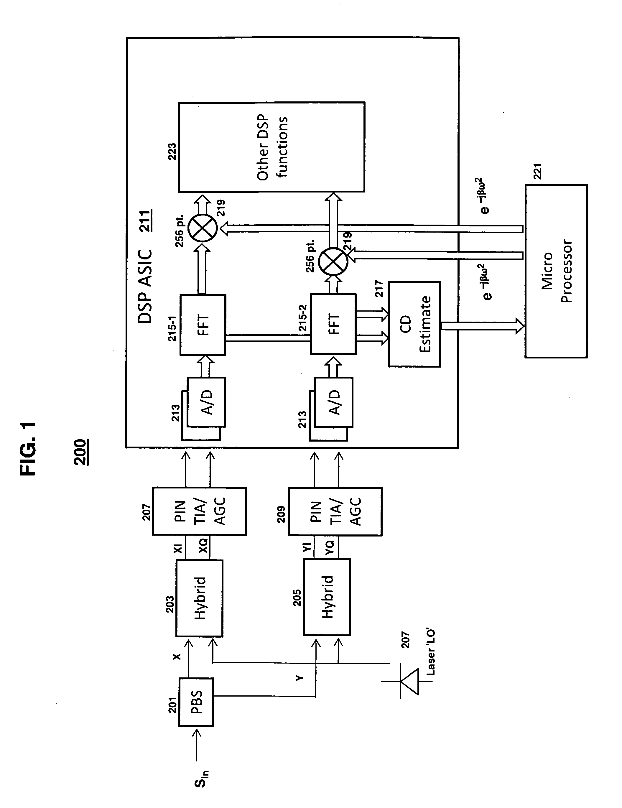
[0037]When a 256-pt FFT is used in a receiver consistent with an exemplary embodiment, the above estimate is satisfactory even if the receiver clock is not locked and there is 100 ppm offset. FIG. 3 depicts the performance of the estimated chromatic dispersion in this embodiment without PMD or other polarization effects with respect to the actual chromatic dispersion for a QPSK modu...


PUM


Abstract

Consistent with the present disclosure, a method and system for estimating chromatic dispersion of an optical signal in a coherent receiver is provided that is insensitive to polarization mode dispersion (PMD) and other polarization effects in the optical communication system. The effects of chromatic dispersion in the optical system are estimated by first calculating a phase shift between a pair of related frequency domain data outputs of a Fourier transform circuit. The calculated phase shift includes a linear phase component that is proportional to the chromatic dispersion, a DC constant phase component, and a data spectrum component. The calculated phase shift is then averaged over a number of clock cycles to remove the data spectrum components. The time averaged result is used to normalize any effects of PMD from the received signal. A slope of the linear phase component as a function of frequency is then calculated and used to estimate the value for chromatic dispersion. The chromatic dispersion estimate is then used to determine a number of coefficients of an inverse frequency response of the chromatic dispersion in the system, and is used to compensate for the chromatic dispersion.

Description

BACKGROUND OF THE DISCLOSURE[0001]Coherent optical communication systems have been developed that provide distinct advantages over more traditional direct detection schemes. In a coherent optical communication receiver, the optical phase and amplitude of a transmitted optical signal can be detected, thus enabling the use of multilevel modulation schemes to increase optical fiber spectral efficiency. Coherent detection provides another advantage over direct detection in that linear impairments of the transmitted optical signal can be compensated for in the receiver using digital filters and other known digital compensation techniques.[0002]Some important linear impairments that can affect the performance of optical communication systems include two forms of signal distortion resulting from chromatic dispersion (CD) and polarization mode dispersion (PMD) of the optical signal. The transmitted optical signal has a finite spectral width such that the spectral components may be transmitt...

Claims


Application Information

Patent Timeline
Patent Type & Authority Applications(United States)
IPC IPC(8): H04B10/06
CPCH04B10/6162H04B10/6161
Inventor SUN, HAN HENRYWU, KUANG-TSAN
Owner INFINERA CORP
Why Eureka
Try Eureka