
Light reactive media

a technology of reactive media and light, applied in the field of light reactive media, can solve the problems of complex preparation and alignment, high cost, and high cost, and achieve the effects of short phosphorescence time, rapid change of image, and long phosphorescence tim

Inactive Publication Date: 2012-05-24
MILES ANTHONY
View PDF3 Cites 8 Cited by
  • Summary
  • Abstract
  • Description
  • Claims
  • Application Information

AI Technical Summary

Benefits of technology

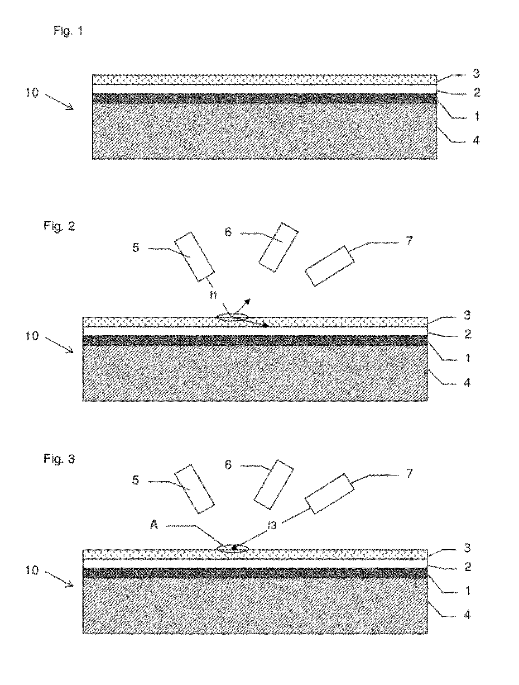
[0009]An advantage of this arrangement is that a visible image may be formed on the first layer using light of the first frequency, and the image may then be ‘fixed’ using light of the second frequency such that subsequent irradiation by the first frequency makes substantially no visible difference to the first layer. Thus, the first layer may be made sensitive to low levels of radiation at the first frequency, so that low power light sources may be used.
[0011]An advantage of this arrangement is that the first layer is protected from the first frequency until an image is to be written to the first layer, whereupon the medium is exposed to the third frequency, prior to writing using the first frequency.
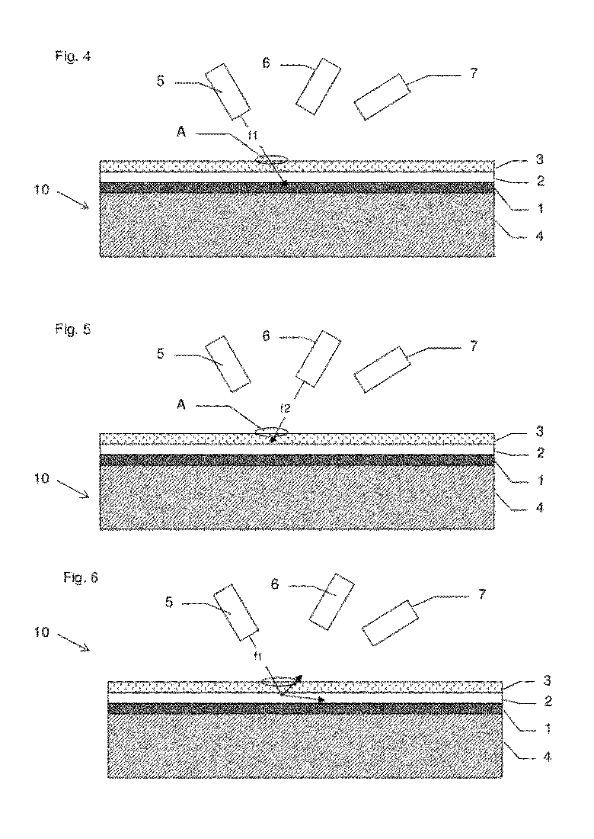
[0017]According to another aspect of the invention, there is provided a method of writing a visible image to a medium, the medium comprising a first layer reactive to electromagnetic radiation of a first frequency to exhibit a visible change, the method comprising exposing the first layer to electromagnetic radiation of the first frequency, and subsequently applying a protective layer over the first layer, the protective layer blocking electromagnetic radiation of said first frequency from acting on the first layer, the visible change being visible through the further layer. An advantage of this arrangement is that the construction of the medium is simplified.
[0024]The method described above does not require a backlight and does not require high-powered laser systems such as laser TV. This method of creating a picture can be used to produce images with long phosphorescing time to provide fixed rewritable images, or short phosphorescing times rapid changes in the image.

Problems solved by technology

The print quality produced by this process is sufficient for that specific purpose and market, but it is unlikely that this process would compete with conventional desktop printers.
CO2 lasers in excess of 10 Watts are used, which are not only extremely expensive and very large, but are also classified as industrial lasers and therefore subject to rigorous safety standards; this precludes them from being used in a desktop application.
This requires complex preparation and alignment when applying the lens sheet.
The complexity of producing lenticular images has prevented mainstream desktop applications.

Method used


Image

  • Light reactive media
  • Light reactive media
  • Light reactive media

Examples


first embodiment

A. First Embodiment

[0047]As shown in FIG. 1, a photoreactive medium 10 according to the first embodiment comprises a substrate 4, of flexible or rigid material. The substrate may be of plastics, paper, wood or fabric, for example. A first layer 1 is applied to the substrate, comprising a material reactive to light at a first frequency f1 to exhibit a visible change, such as a change in colour or shade. The first layer 1 may comprise a plurality of materials that each exhibit a different colour change, either arranged in a spatially distinct pattern, or sensitive to different frequencies within the range of frequency f1, to enable colour imaging.

[0048]A second layer 2 is applied over the imaging layer, comprising a material that allows frequency f1 to pass through until exposed to a light of a second frequency f2, whereupon the material changes state so as to block frequency f1. A third layer 3 is applied over the first protective layer 3, comprising a material that blocks frequency ...


PUM


Abstract

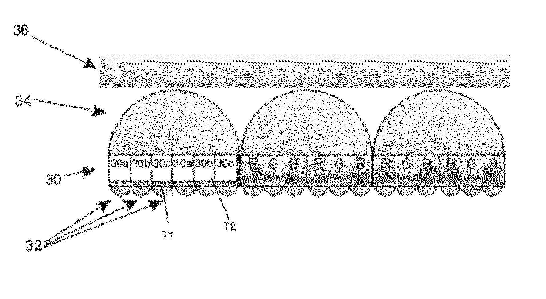
A light reactive medium comprises an imaging layer reactive to radiation of a first frequency to exhibit a visible change, and a further layer above the imaging layer, the further layer being changeable from being substantially transparent to said first frequency to being substantially opaque to said first frequency, in response to electromagnetic radiation of a second frequency substantially different from the first frequency, the at least one other layer being at least partially transparent to visible light reflected from the imaging layer while being opaque to said first frequency. Also disclosed is a lenticular imaging method in which a lenticular layer is provided over the imaging layer, and images to be viewed from different directions are written using light incident at different directions. Also disclosed is a phosphorescent display that may be used to display lenticular images.

Description

BACKGROUNDField of the Invention[0001]The present invention relates to light reactive media and to methods of writing images to such media.BACKGROUND OF THE INVENTION[0002]There are a number of laser reactive coatings available that are primarily for use in the ‘just in time’ packaging market. These coatings are usually white and when activated by a laser at a particular frequency exhibit a colour change, for example to produce text, barcodes and / or images. The print quality produced by this process is sufficient for that specific purpose and market, but it is unlikely that this process would compete with conventional desktop printers.[0003]The coatings require a large amount of laser energy to produce the chemical reactions that evoke the colour change in the area to be printed. CO2 lasers in excess of 10 Watts are used, which are not only extremely expensive and very large, but are also classified as industrial lasers and therefore subject to rigorous safety standards; this preclu...

Claims


Application Information

Patent Timeline
IPC IPC(8): H01J1/62G03F7/20G03F7/004G02B30/27
CPCG02B27/2214G03B21/60G03B33/14G03C9/02G03C1/732G03C7/14G03C1/685G03B21/602G03B25/00G03B25/02G02B30/27
Inventor MILES, ANTHONY
Owner MILES ANTHONY
Learn More