
Data center network system and packet forwarding method thereof

Active Publication Date: 2012-05-24
IND TECH RES INST
View PDF10 Cites 38 Cited by
  • Summary
  • Abstract
  • Description
  • Claims
  • Application Information

AI Technical Summary

Benefits of technology

[0014]The disclosure is directed to a data center network system and a packet forwarding method, by which the number of machines can be effectively expanded under the Ethernet protocol.
[0023]According to the above descriptions, utilization of the forwarding table entries can be greatly reduced, so as to effectively increase the number of virtual machines configured in the data center network system.

Problems solved by technology

However, the cost for constructing and maintaining network equipments is considerable.
Therefore, it is unnecessary for the corporation to construct a machine room for containing hardware or telecommunication equipments, instead, the corporation can place the related machines in the machine room owned by the network data center provider or rent the machines owned by the network center provider.
Therefore, it is an important issue for the related practitioner to design an efficient, liable and manageable network based on an economically reasonable design.
Although the Ethernet technology can be conveniently applied to the data center network, is has a problem of scalability.
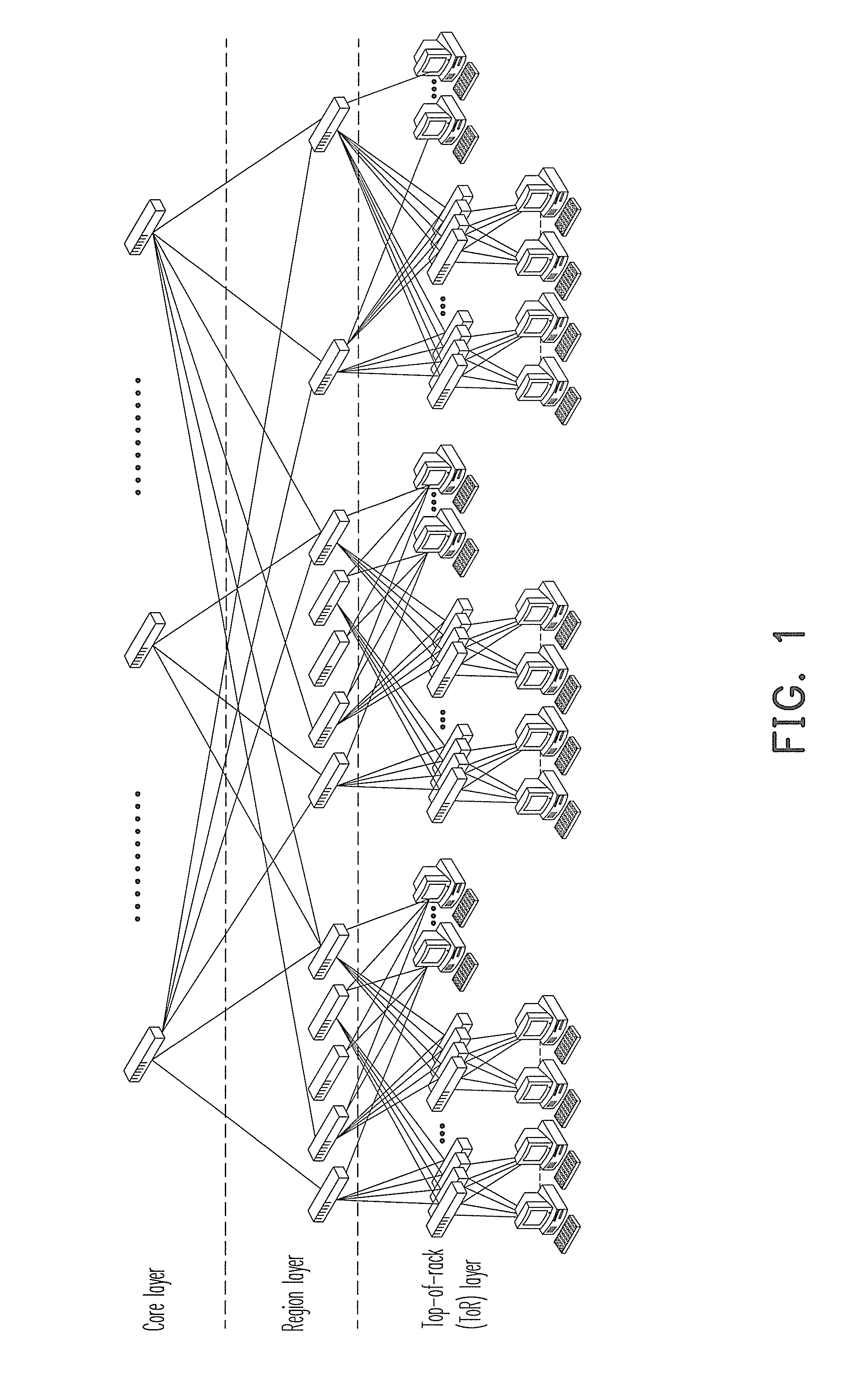
However, the forwarding table configured in a commodity Ethernet switch can only record 16K-32K forwarding table entries, so that the Ethernet can only contain several hundreds to several thousands of the physical machines, generally.
Now, the Ethernet will not support communication of such large amount of the physical machines or the virtual machines.

Method used


Image

  • Data center network system and packet forwarding method thereof
  • Data center network system and packet forwarding method thereof
  • Data center network system and packet forwarding method thereof

Examples


first exemplary embodiment

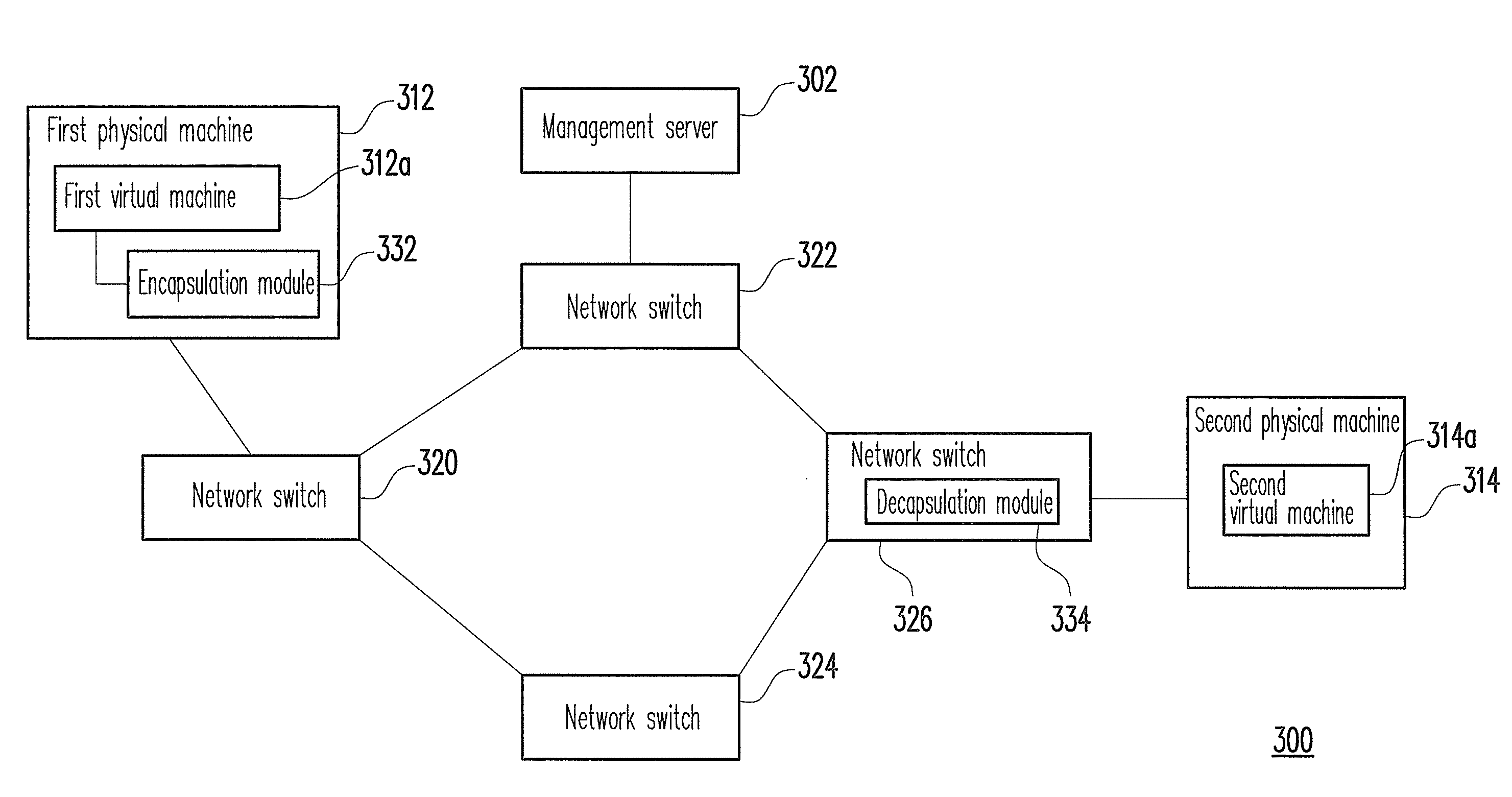
[0039]FIG. 3 is a schematic diagram illustrating a data center network system according to a first exemplary embodiment of the disclosure.

[0040]Referring to FIG. 3, the data center network system 300 includes a management server 302, a first physical machine 312, a first virtual machine 312a, a second physical machine 314, a second virtual machine 314a, a network switch 320, a network switch 322, a network switch 324 and a network switch 326.

[0041]The management server 302 is configured for managing all of the connected physical machines, the virtual machines and the network switches in the data center network system 300. For example, the management server 302 is a directory server, and stores related management information, where the management information includes related information of the virtual machines operated in the physical machines and information of top-of-rack (ToR) network switches connected to the physical machines. In the present exemplary embodiment, the management ...

second exemplary embodiment

[0069]FIG. 7 is a schematic diagram illustrating a data center network system according to a second exemplary embodiment of the disclosure.

[0070]Referring to FIG. 7, the data center network system 700 includes a management server 702, a first physical machine 712, a first virtual machine 712a, a second physical machine 714, a second virtual machine 714a, a network switch 720, a network switch 722, a network switch 724 and a network switch 726.

[0071]The first physical machine 712 has an encapsulation module 732. Moreover, the virtual physical machine 712a and the second virtual machine 714a are respectively run on the first physical machine 712 and the second physical machine 714 for providing corresponding services. The management server 702, the first physical machine 712, the encapsulation module 732, the first virtual machine 712a and the second virtual machine 714a are respectively the same to the management server 302, the first physical machine 312, the encapsulation module 33...

third exemplary embodiment

[0085]In the first exemplary embodiment, the decapsulation procedure is executed by the network switch in the data center network system, and in the second exemplary embodiment, the decapsulation procedure is executed by the physical machine in the data center network system. In the third exemplary embodiment, a part of the data packets is decapsulated by the network switch, and another part of the data packets is decapsulated by the physical machine.

[0086]FIG. 9 is a schematic diagram illustrating a data center network system according to a third exemplary embodiment of the disclosure.

[0087]Referring to FIG. 9, the data center network system 900 includes a management server 702, a first physical machine 712, a first virtual machine 712a, a second physical machine 714, a second virtual machine 714a, a third physical machine 912, a third virtual machine 912a, a network switch 720, a network switch 722, a network switch 726 and a network switch 902.

[0088]Structures and functions of th...


PUM


Abstract

A data center network system and a packet forwarding method are provided. The data center network includes a management server and a plurality of machines containing physical machines and virtual machines. The management server configures a logical media access control (MAC) address for each of the machines, wherein most significant bytes of each of the logical MAC addresses are set as 0. When a data packet is about to be sent from a physical machine, the physical machine executes an encapsulation procedure on the data packet for forwarding the data packet to an intermediate node between a transmitter and a receiver of the data packet, and the intermediate node executes a decapsulation procedure on the data packet for forwarding the data packet to the true receiver. Accordingly, the number of virtual machines exposed to the forwarding table of Ethernet switches can be effectively reduced.

Description

BACKGROUND[0001]1. Field of the Disclosure[0002]The disclosure relates to a data center network system and a packet forwarding method.[0003]2. Description of Related Art[0004]Along with development of network technology, corporations widely use networks to provide services or exchange information. However, the cost for constructing and maintaining network equipments is considerable. Therefore, an operation mode of a network data center is gradually developed. The so-called network data center is referred to a large-scale data storage center, which can provide services such as host collocation, host rent, remote backup, and system and network management, etc. For example, after a corporation rent a host space or purchase a host collocation service from a network data center provider, the corporation can arbitrarily access and manage all information in their remote host space. Therefore, it is unnecessary for the corporation to construct a machine room for containing hardware or telec...

Claims


Application Information

Patent Timeline
IPC IPC(8): G06F15/16G06F9/455
CPCH04L12/4633H04L45/04H04L45/00H04L45/76
Inventor CHIUEH, TZI-CKERHSU, MING-CHAOTU, CHENG-CHUN
Owner IND TECH RES INST
Learn More