Cutting Arrangement Having a Tip-to-Tip Blade Arrangement

Inactive Publication Date: 2012-05-31
DIENES CORP
View PDF11 Cites 13 Cited by
  • Summary
  • Abstract
  • Description
  • Claims
  • Application Information

AI Technical Summary

Benefits of technology

[0011]Since the cutting arrangement of the present invention relates to a constantly moving web of material that will impart varying loads on the knives when slitting, the present invention also embodies an adaptive control technology with the following features: individual drive motors for each of the knife blades; and a constant side load force control for each knife blade that allows for knife blade side force load monitoring, whic

Problems solved by technology

If material having a great thickness, or in particular a stack of a plurality of superimposed lengths of material, which similarly have a corresponding overall material thickness, is to be cut or divided by a cutting arrangement in a cut, there results, with a cutting arrangement that is comprised, for example, of an upper blade embodied as a circular blade and a lower blade embodied as

Method used


Image

  • Cutting Arrangement Having a Tip-to-Tip Blade Arrangement
  • Cutting Arrangement Having a Tip-to-Tip Blade Arrangement
  • Cutting Arrangement Having a Tip-to-Tip Blade Arrangement

Examples


Embodiment Construction

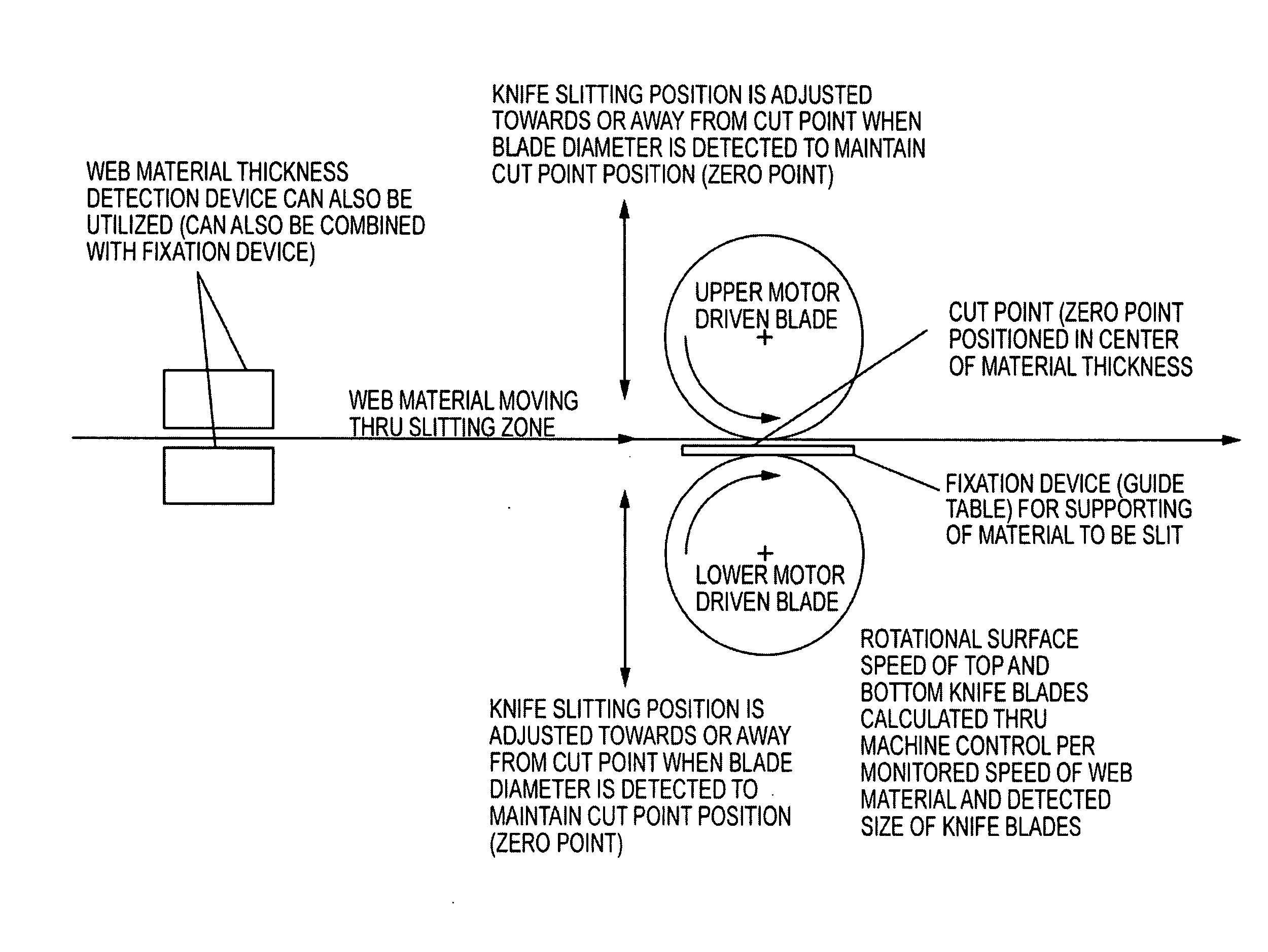
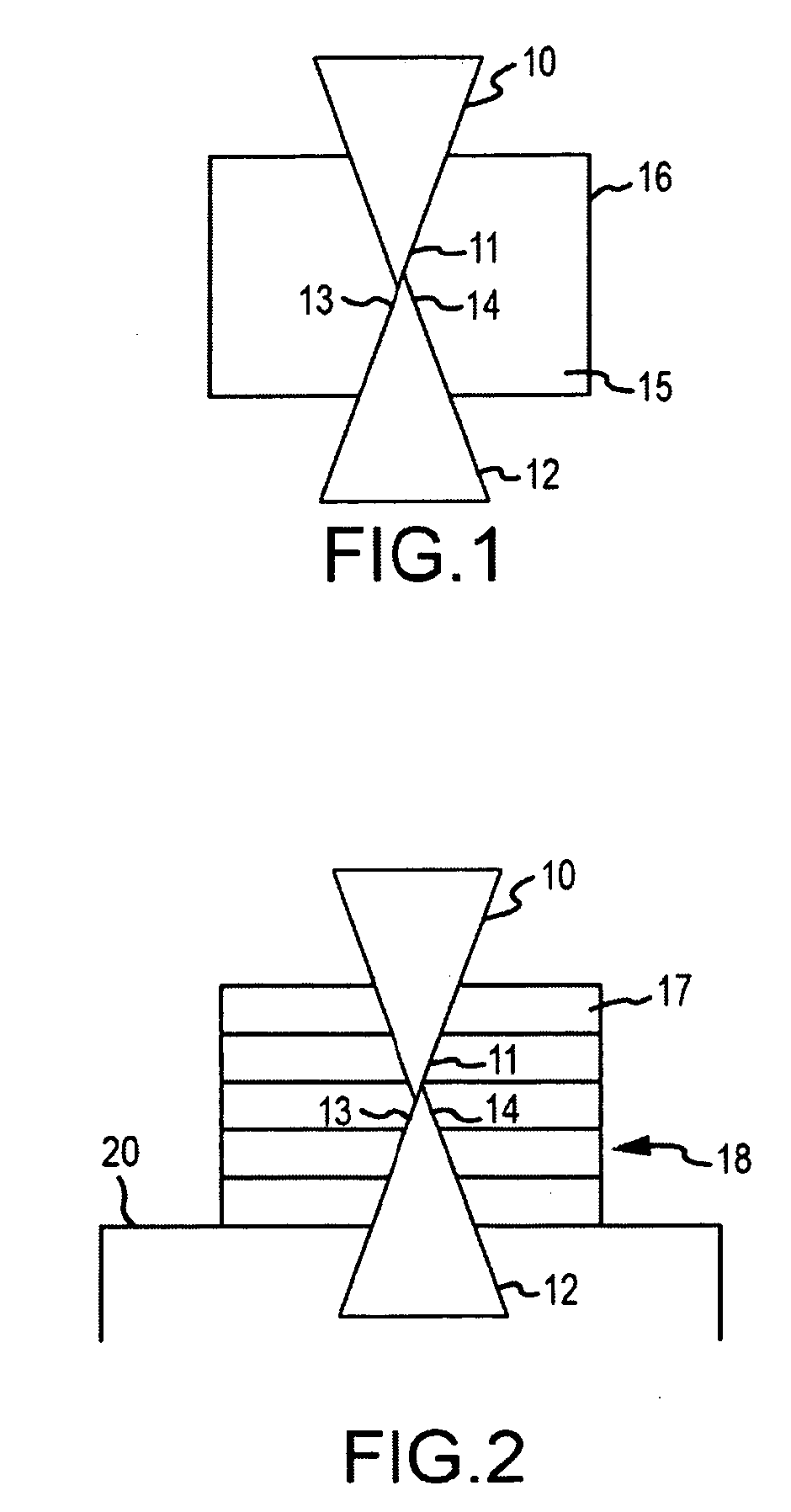
[0021]As can be seen from FIG. 1, the blade or cutting arrangement, which is provided for cutting a band or length of material 15 having a great material thickness 16, is comprised of an upper blade 10 and a lower blade 12, whereby each of the upper blade 10 and lower blade 12 has a sharp blade or cutting edge 11 or 13 respectively. In this connection, upper blade 10 and lower blade 12 are disposed or positioned relative to one another in such a way that an overlap zone 14 of the two cutting edges 11, 13 results. To achieve the best possible cutting result, upper blade 10 and lower blade 12 are positioned in such a way that the center of the overlap zone 14 is disposed in the middle of the material thickness of the length of material 15.

[0022]In the embodiment illustrated in FIG. 2, the material that is to be cut or divided by the upper blade 10 and the lower blade 12 is comprised of a stack 18 of individual bands or lengths of material 17 that are disposed one above the other and t...


PUM

PropertyMeasurementUnit
Lengthaaaaaaaaaa
Thicknessaaaaaaaaaa
Pressureaaaaaaaaaa

Abstract

A cutting arrangement for longitudinally cutting material includes two blades disposed across from one another and which cooperate during cutting. Each blade is embodied as a circular blade having a sharp cutting edge and supported by an adjusting or placement mechanism. During the cutting process, the circular blades are positioned by the adjusting or placement mechanisms so that the cutting edges overlap one another to form an overlap zone, the center of which coincides with the middle of the material that is to be cut. An adaptive control assembly includes individual drive motors for driving each blade and enables constant side load force control for each blade, such that side load pressures are adjustable in response to changes in web sped, web tension, and blade condition in real time. Automatic blade diameter sensors calculate the zero point of the cut, determine the appropriate blade speed and automatically set the overlap.

Description

[0001]The present application is a continuation-in-part of U.S. application Ser. No. 11 / 841,252. The instant application should be granted the priority date of Aug. 19, 2006, the filing date of the corresponding German patent application 20 2006 012 820.4.BACKGROUND OF THE INVENTION[0002]The present invention relates to a cutting arrangement for the longitudinal cutting or division of material and includes two blades that are disposed across from one another and that during the cutting process cooperate with one another.[0003]If material having a great thickness, or in particular a stack of a plurality of superimposed lengths of material, which similarly have a corresponding overall material thickness, is to be cut or divided by a cutting arrangement in a cut, there results, with a cutting arrangement that is comprised, for example, of an upper blade embodied as a circular blade and a lower blade embodied as a grooved counter blade, the problem that the cutting blade must penetrate ...

Claims


Application Information

Patent Timeline
IPC IPC(8): B26D1/24B26D7/06B26D5/02B26D5/00
CPCB26D1/0006B26D5/02B26D2001/0066B26D2001/0046B26D2001/0053B26D7/2635Y10T83/7801Y10T83/6603Y10T83/538Y10T83/7843Y10T83/173Y10T83/175Y10T83/178Y10T83/7797Y10T83/148Y10T83/783Y10T83/0581
Inventor SUPE-DIENES, RUDOLF
Owner DIENES CORP
Why Eureka
Try Eureka