Patient interface systems

a patient interface and system technology, applied in the field of patient interface systems, can solve problems such as health risks, lack of stability, and improvement or decrease of comfort or effectiveness, and achieve the effect of convenient use of headgear assemblies and comfor

Active Publication Date: 2012-05-31
RESMED LTD
View PDF5 Cites 141 Cited by
  • Summary
  • Abstract
  • Description
  • Claims
  • Application Information

AI Technical Summary

Benefits of technology

[0029]One aspect of the present technology is a quiet comfortable patient interface for treatment of respiratory disorders. Another aspect of the present technology is a comfortable and easier t

Problems solved by technology

Apparently subtle changes may improve or decrease comfort or effectiveness.
While millions of people suffer from the condition of sleep disordered breathing, many fail to comply with therapy because of problems with comfort, ease of use, stability, leak, and obtrusiveness, and thus expose themselves to health

Method used


Image

  • Patient interface systems
  • Patient interface systems
  • Patient interface systems

Examples


first embodiment

3.2.4.1 Patient Interface Structure Including Linking Element—First Embodiment

[0197]Referring to FIGS. 8a and 8b, a patient interface structure according 32 according to another sample embodiment may comprise a seal 2 comprising a nozzle assembly 3 having nasal pillows 4. The patient interface structure 32 may include an optional linking portion or element 47 configured to link tension forces applied by the seal positioning and stabilizing structure from one side of the patient interface structure 32 to the other side in order to isolate forces applied by the seal positioning and stabilizing structure at the top portion 6t of the flexible base 6, and thereby isolate tube drag forces at the lower portion 6l of the flexible base 6 of the patient interface structure 32. By isolating forces in such a way, the sealing zones 8a of the nasal pillows 4 of the seal 2 are stabilized against the patient's nares in use. In some forms of the technology, there may be no physical linking element. ...

second embodiment

3.2.4.2 Patient Interface Structure Including Linking Element—Second Embodiment

[0203]As shown in the sample embodiment of the patient interface structure shown in FIG. 8a, the linking element 47 may extend across the entire top portion 6t of the flexible base 6, from connector 50 to connector 50, and including the entire width. See, for example, W1 in FIG. 17a. According to another sample embodiment of the patient interface structure 32 shown in FIG. 8c, the linking element 47 may extend over a section, or sections, of the top portion 6t of the flexible base 6, for example only the section of the top portion 6t between the nasal pillows 4. The linking element 47 may cover a fraction of the width of the top portion 6t, for example half the width. The tension linking element 47 may cover a section, or sections, of the top portion 6t as long as it is sufficient to isolate the forces as described above.

third embodiment

3.2.4.3 Patient Interface Structure Including Linking Element—Third Embodiment

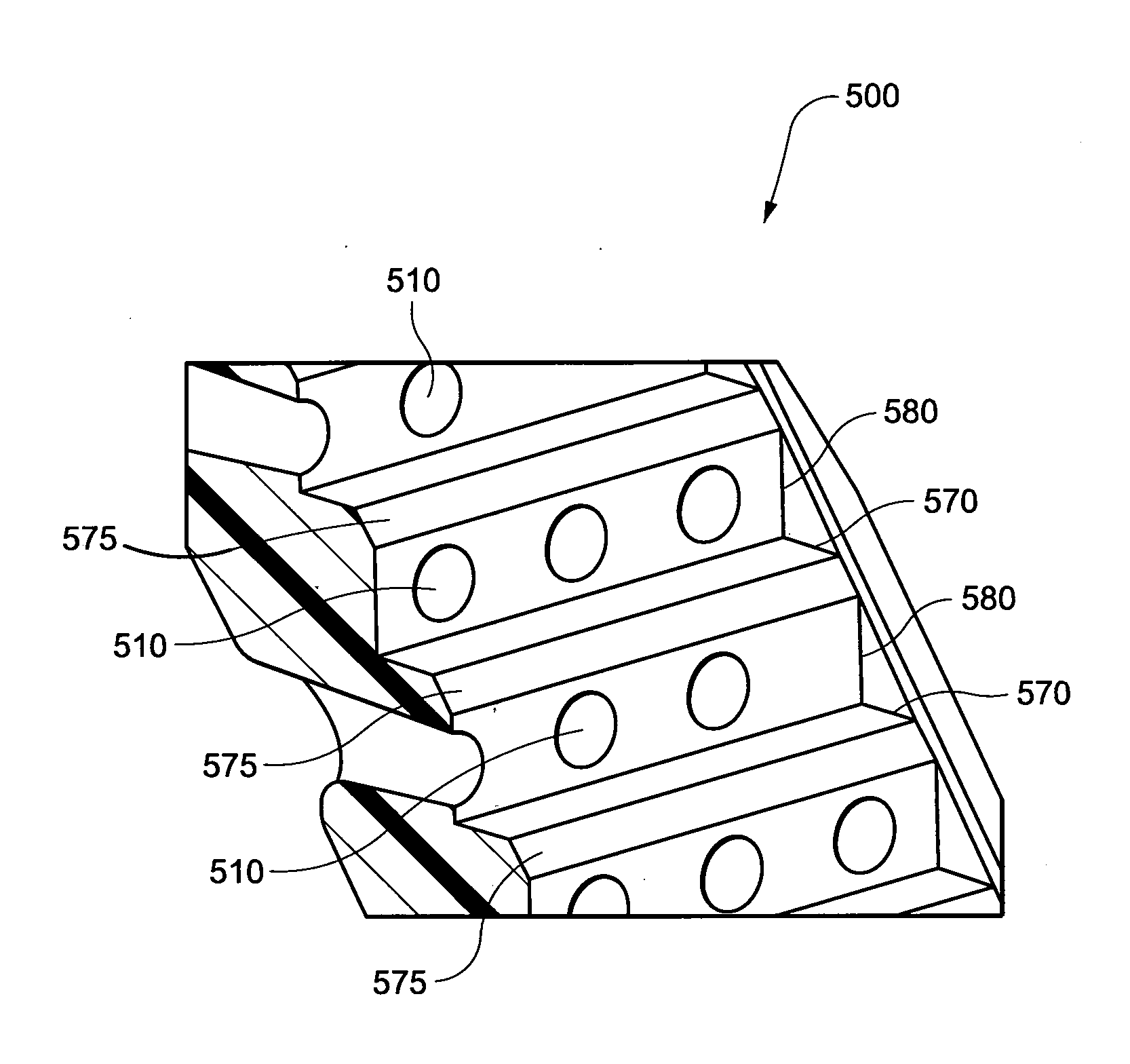
[0204]Referring to FIG. 8d, the linking element may be formed as a series of ridges 47a. The number of ridges 47a may be determined in order to sufficiently isolate forces as described above. As shown in FIG. 8d, the ridges 47a may be provided to the top portion 6t only between the nasal pillows 4. The ridges 47a may be thicker than the top portion 6t. The ridges 47a may be generally circular or rectangular or any other shape. The ridges 47a may extend upwards and / or downwards from the top portion 6t. The ridges 47a may also be formed from a material of higher hardness than that used to form top portion 6t, for example higher durometer silicone, or metal. The ridges 47a may be formed in one piece with the patient interface structure 32, or may be retrofitted to the patient interface structure 32. For example, the linking element, e.g. the ridges 47a, may be adhesively attached to the patient interface stru...


PUM


Abstract

A headgear for use with a patient interface for delivering a flow of breathable gas to a patient includes at least a strap (741) adapted to position the patient interface in sealing engagement with the patient's airways. The strap is constructed from an elastomer and a first side of the strap includes a first region (215) on a portion of its surface that is textured to reduce friction with objects contacting the strap. A textured surface coating for a portion of an elastomer strap included in a headgear system is adapted to contact the skin of a patient, when in use, and the coating has a Ra value greater than zero. A vent (500) for use with a patient interface for delivering a flow of breathable gas to a patient includes a plurality of rises (580) and runs (570) in a stepped arrangement; and a plurality of holes (510) in the stepped arrangement for the venting of gas.

Description

CLAIM FOR PRIORITY[0001]This application claims priority to Australian Applications 2009903686 and 2009904389, filed Aug. 7, 2009 and Sep. 9, 2009, respectively, and to U.S. application Ser. No. 12 / 763,467, filed Apr. 20, 2010, the entire contents of each being incorporated herein by reference.CROSS REFERENCE TO RELATED APPLICATIONS[0002]U.S. application Ser. No. 12 / 763,467 is a continuation-in-part of International Application PCT / AU2008 / 001557, filed Oct. 22, 2008, which claims priority to Australian Applications 2007905737 and 2007906276, filed Oct. 22, 2007 and Nov. 16, 2007, respectively, and U.S. Applications 61 / 031,173 and 61 / 129,982, filed Feb. 25, 2008 and Aug. 4, 2008, respectively, the entire contents of each being incorporated herein by reference. U.S. application Ser. No. 12 / 763,467 is also a continuation-in-part of U.S. Application 29 / 335,698, filed Apr. 20, 2009, the entire contents of which are incorporated herein by reference.FIELD OF THE INVENTION[0003]The technolo...

Claims


Application Information

Patent Timeline
IPC IPC(8): A61M16/06
CPCA61M16/06A61M16/0666A61M16/0683A61M16/0611A61M2205/42A61M2210/0618A62B9/04A61M16/0816A61M16/0825A61M16/0622
Inventor RUMMERY, GERARD MICHAELHENRY, ROBERT EDWARDHILL, PHOEBE KATHERINEHURST, ANDREWNURSE, PHILIP MICHAEL
Owner RESMED LTD
Why Eureka
Try Eureka