
Thermoelectric generator apparatus with high thermoelectric conversion efficiency

a generator and thermoelectric technology, applied in the direction of thermoelectric devices with peltier/seeback effect, basic electric elements, electric devices, etc., can solve the problems of important development of renewable energy technologies, and achieve high thermal conductivity, high efficient thermal conductivity, and increase the effect of heat flux

Inactive Publication Date: 2012-05-31
IND TECH RES INST
View PDF5 Cites 20 Cited by
  • Summary
  • Abstract
  • Description
  • Claims
  • Application Information

AI Technical Summary

Benefits of technology

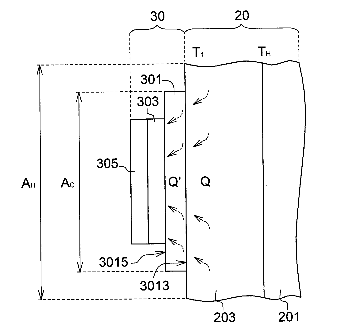
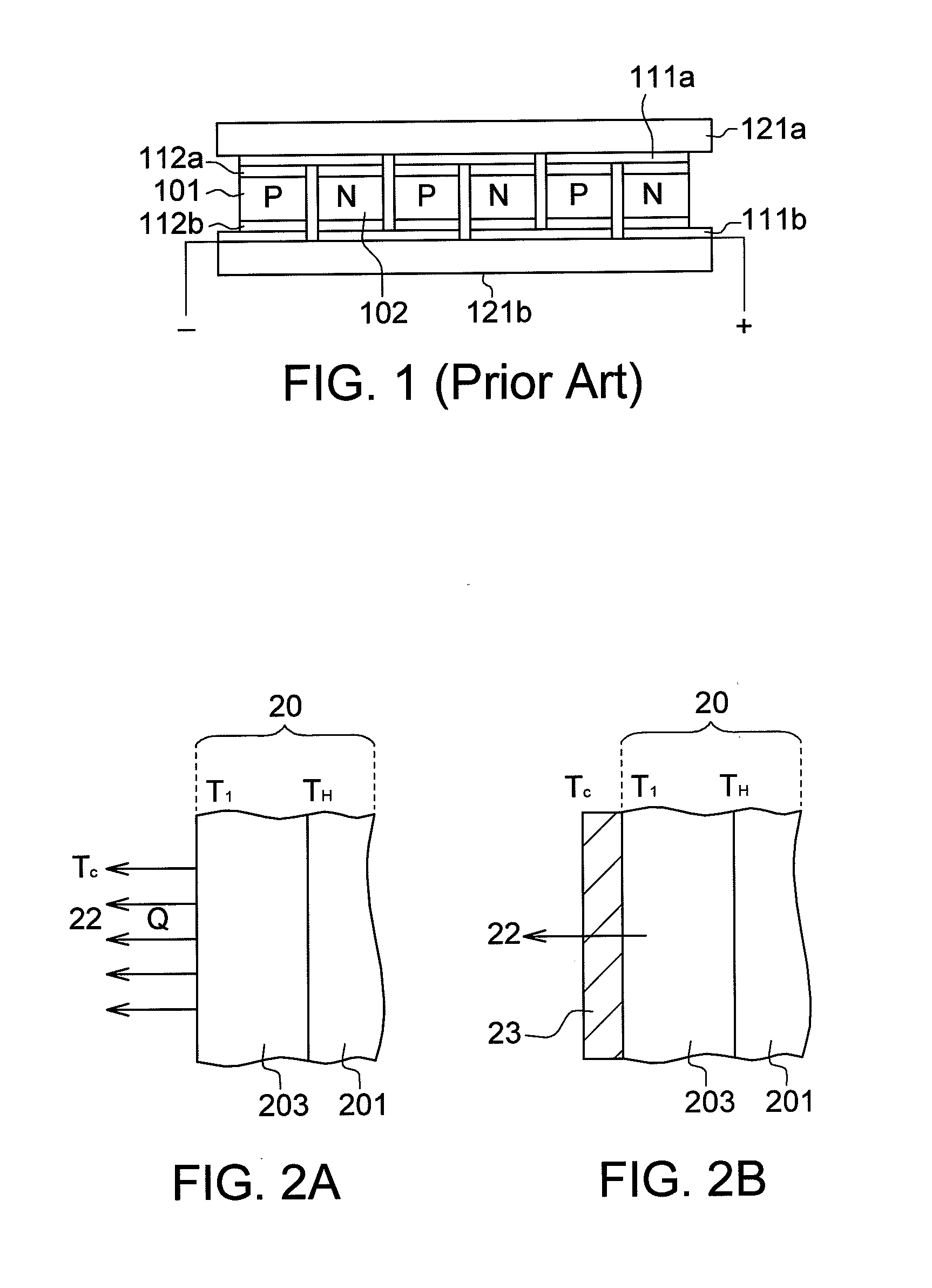
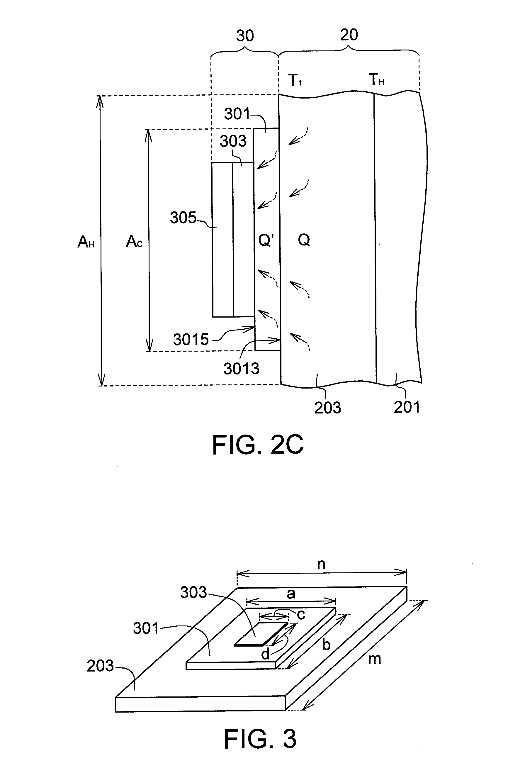
[0011]The disclosure is directed to a thermoelectric generator apparatus, which uses a heat concentrator with high thermal conductivity as a medium disposed between the hot side substrate of a thermoelectric module and a heat source. The heat generated by the heat source is concentrated on the heat concentrator with high efficient thermal conductivity and flows to the hot side of the thermoelectric module for increasing the heat flux (Q′) passing the thermoelectric module and the hot side temperature of the thermoelectric module. Consequently, the thermoelectric conversion efficiency η is improved, and the electric power P generated by the thermoelectric module is increased.

Problems solved by technology

The problem of energy shortage has made the development of renewable energy technologies become an important issue.

Method used


Image

  • Thermoelectric generator apparatus with high thermoelectric conversion efficiency
  • Thermoelectric generator apparatus with high thermoelectric conversion efficiency
  • Thermoelectric generator apparatus with high thermoelectric conversion efficiency

Examples


Embodiment Construction

[0027]The thermoelectric generator apparatus of the disclosure uses the principle that a direct current is generated when the thermoelectric generator apparatus has two substrates with different temperatures, and has a wide range of application such as power generation by waste heat generated by industrial processes, high temperature exhaust of vehicle or vessel engines, hot springs and terrestrial heat. Take the high temperature furnace commonly used in industrial processes for example. The temperature on the outer wall of the furnace normally ranges between 100˜250° C. When a thermoelectric module is installed on the furnace wall, one substrate of the thermoelectric module directly contacts the furnace wall and serves as a hot side, and the other substrate serves as a cold side by way of air cooling or water cooling. Meanwhile, the cold side and the hot side of the thermoelectric module with temperature difference is capable of generating a direct current. The magnitude of the pow...


PUM

PropertyMeasurementUnit
temperatureaaaaaaaaaa
areaaaaaaaaaaa
heightaaaaaaaaaa

Abstract

A thermoelectric generator apparatus disposed on a high-temperature surface of an object (as a heat source), at least includes a heat concentrator, a thermoelectric module and a cold-side heat sink. The heat concentrator has a top surface and a bottom surface contacting a high-temperature surface of the object, and an area of the bottom surface is smaller than that of the high-temperature surface. The thermoelectric module is disposed on the top surface of the heat concentrator. The cold-side heat sink is disposed on the thermoelectric module. Heat generated by the heat source is concentrated on the heat concentrator and flows to the hot side of the thermoelectric module for increasing the heat flux (Q′) passing the thermoelectric module and the hot side temperature of the thermoelectric module. Consequently, the thermoelectric conversion efficiency (η) is improved, and the power generation of the thermoelectric module is increased.

Description

[0001]This application claims the benefit of Taiwan application Serial No. 099141271, filed Nov. 29, 2010, the subject matter of which is incorporated herein by reference.BACKGROUND[0002]1. Technical Field[0003]The disclosure relates in general to a thermoelectric generator apparatus, and more particularly to a thermoelectric generator apparatus with high thermoelectric conversion efficiency.[0004]2. Description of the Related Art[0005]The thermoelectric generator module possesses the characteristics of thermoelectric conversion, that is, converts thermal energy to electrical energy and vice versa. Due to the characteristics of thermoelectric conversion, the thermoelectric generator module can be used in cooling / heating and power generation. When a direct current is applied to a thermoelectric conversion device, heat absorption and heat dissipation will occur to the two ends of the device, and such principle can be used in the cooling / heating technologies. When the two ends of the t...

Claims


Application Information

Patent Timeline
Patent Type & Authority Applications(United States)
IPC IPC(8): H01L35/30H10N10/10H10N10/13H10N10/17H10N10/80
CPCH01L35/30H10N10/13
Inventor CHU, HSU-SHENHWANG, JENN-DONG
Owner IND TECH RES INST
Learn More