Two-phase heat transfer device for heat dissipation

a heat transfer device and two-phase technology, applied in the direction of indirect heat exchangers, electrical equipment construction details, lighting and heating apparatus, etc., can solve the problems that conventional heat transfer devices such as heat sinks, heat pipes, and vapor chambers may not meet the requirements of freedom of design, thermal resistance and dissipation heat flux, etc., to achieve enhanced heat dissipation efficiency, increase the heat dissipation of two-phase heat transfer devices, and facilitate production

Pending Publication Date: 2021-04-29
ABB (SCHWEIZ) AG
View PDF4 Cites 1 Cited by
  • Summary
  • Abstract
  • Description
  • Claims
  • Application Information

AI Technical Summary

Benefits of technology

[0025]With regard to the variation of density, the variation of porosity and / or the variation of the size along the path, the density, the porosity and / or the size of the void may be described by a mathematical function depending on at least two parameters. Preferably the mathematical function depends on two parameters. Expressed in a mathematical formula, the mathematical function may be v=f(x,y), or preferably v=f(x,y,z), wherein v is the density, the porosity and / or the size of the void and x, y and z are the parameters. The parameters may be positional parameters, that may dedicate the position of a point in a two- or three-dimensional coordinate system for example along the path through the main body. In particular, the mathematical function f(x,y,z) describing the density, the porosity and / or the size of the void for a three-dimensional object as the main body may be a mathematical function having a certain symmetry. For example, the function f(x,y,z) may be a function of an ordered lattice, e.g. a quadratic or hexagonal lattice. Alternatively, it may be a function of a stochastic foam, or a minimal surface, for example a Schwarz D, Gyroid. Such an arrangement of voids in the main body forming the multi-dimensional void network may increase the heat dissipation of the two-phase heat transfer device and may ease producibility.
[0026]With regard to the sizes of the voids, a two-phase heat transfer device may be provided wherein the voids have sizes in a first size range and the voids have sizes in a second size range, and wherein a size distribution of the voids shows at least two distinct maxima. In other words, the voids of the multi-dimensional void network may not all have the same size, but may have different sizes. Considering all different sizes of the voids, the sizes may lie in two or more size ranges, i.e. in a first size range and in a second size range. Preferably, the first size range may lie between 5 μm to 200 μm, more preferably between 20 μm to 150 μm. Preferably, the second size range may lie between 75 μm to 2000 μm, more preferably between 100 μm to 500 μm. Hence, the first size range and second size range and all consecutive size ranges may overlap. However, the size distribution preferably shows at least two distinct maxima, preferably one maximum in the first size range and the other maximum in the second size range. By having voids with sizes in two size ranges with two distinct maxima in the size distribution, the two-phase heat transfer device may show an enhanced heat dissipation efficiency. The first size range may control the direction of the flow of the heat transfer medium along the path based on the variation in capillary action, as mentioned above. The second size range, with voids having on average a larger size, may increase the flow rate of the liquid phase and may also reduce vapor resistance flow rate. Furthermore, having voids with sizes in the second size range may increase the overall cooling efficiency of the two-phase heat transfer device.
[0027]With regard to the heat transfer medium and according to a preferred embodiment the heat transfer medium may comprise water, ammonia, methanol, ethanol, isopropanol, ethylamine, pentane, acetone and / or a refrigerant fluid. The refrigerant fluid may be one of the refrigerant fluids which has an ASHRAE designated number for example R123 and / or R1233zd. The American Society of Heating, Refrigerating and Air-Conditioning Engineers (ASHRAE) assigns an R number which is determined systematically according to the molecular structure of the refrigerant fluid. The heat transfer medium may be chosen according to the temperature at which the two-phase heat transfer device may operate. It may be one of the above compounds or it may be a mixture thereof. Since the main body of the two-phase heat transfer device preferably is formed in an additive manufacturing step and / or the main body is formed as a one-piece component, the two-phase heat transfer device is very robust. Therefore, high pressure heat transfer media, as ammonia, may be used, which in turn may enhance the heat flux of the two-phase heat transfer device.

Problems solved by technology

Conventional heat transfer devices as heat sinks, heat pipes, and vapor chambers may not be able to meet the requirements on freedom of design of the heat transfer device, thermal resistance and dissipated heat flux.

Method used


Image

  • Two-phase heat transfer device for heat dissipation
  • Two-phase heat transfer device for heat dissipation

Examples


Embodiment Construction

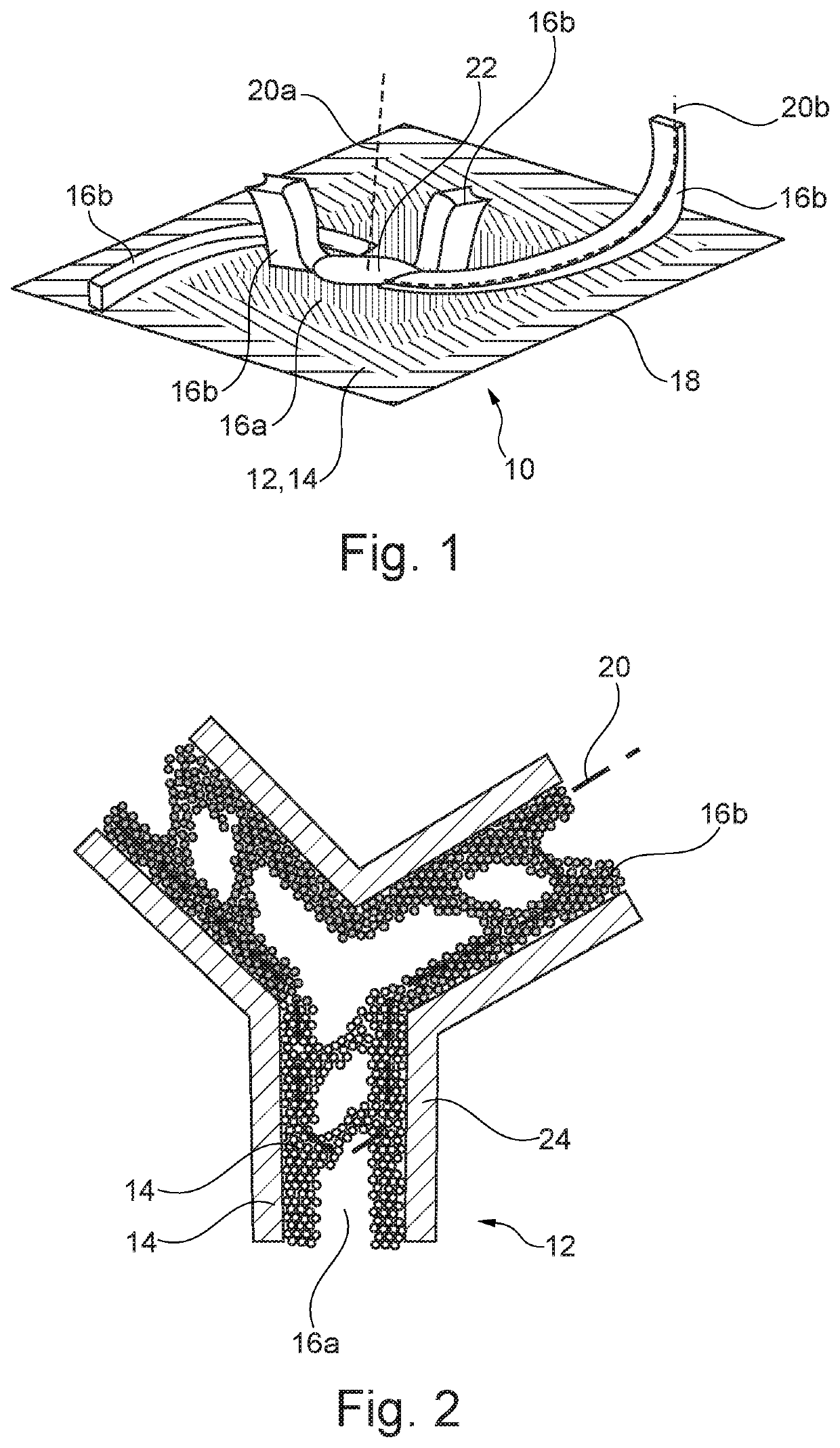
[0051]FIG. 1 shows show a schematic perspective view of a of a two-phase heat transfer device 10 according to a first embodiment of the invention.

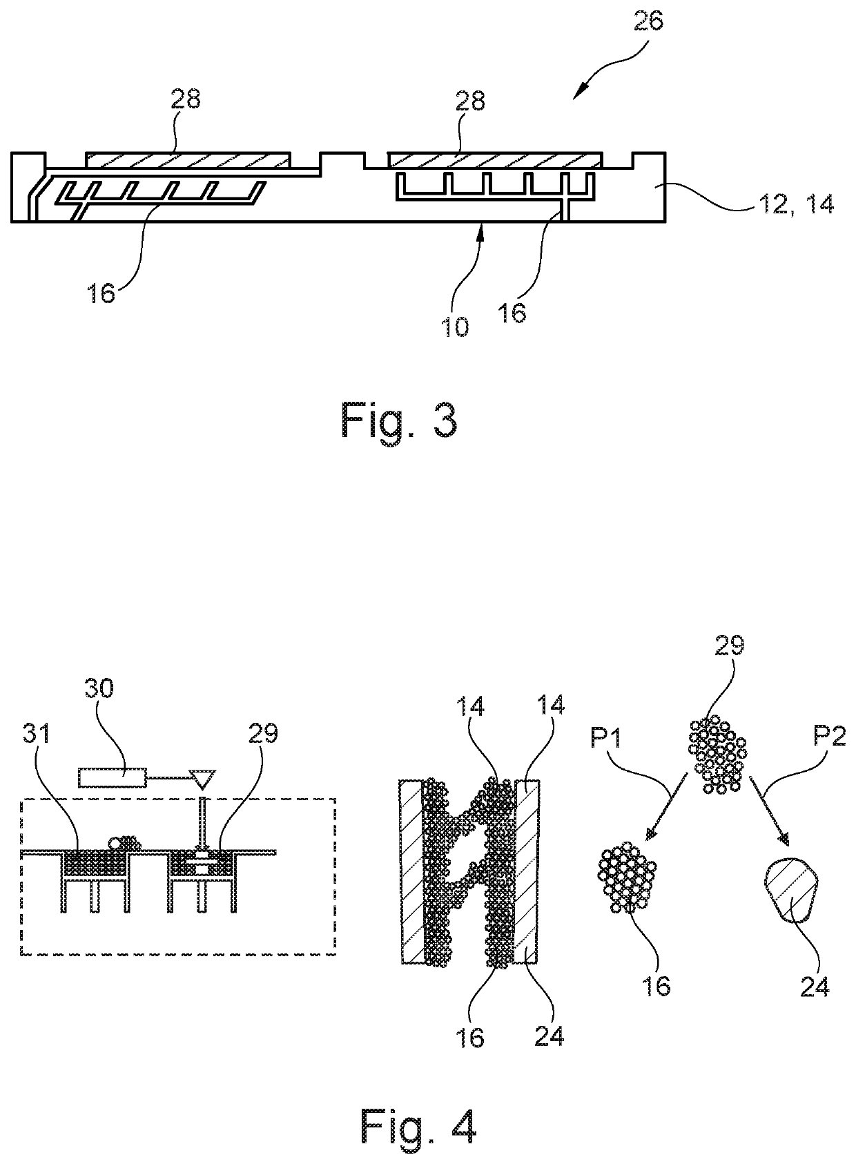
[0052]As can be seen in FIG. 1 the two-phase heat transfer device 10 comprises a main body 12, which is formed from a body material 14. In this embodiment the body material 14 comprises pure copper, bronze, brass, CuCrZr, CuNiSi(Cr), 1xxx / 2xxx / 6xxx series aluminum, AlSi7Mg, AlSi10Mg, AlSi12, Scalmalloy, Al6061, Al—Cu, pure titanium, Ti6Al4V, steel 316L, steel 17-4PH, Inconel 618, Inconel 725 and / or maraging steel. As can easily be seen in FIG. 1, the main body 12 comprises a multi-dimensional void network 16, in this embodiment a three-dimensional void network. The multi-dimensional void network 16 is formed by holes, pores and / or pipes in short voids in the main body 12. Within the multi-dimensional void network 16 the main body 12 is free of the body material 14. The body material 14 of the main body 12 has a porous structure for forming...


PUM


Abstract

The invention relates to a two-phase heat transfer device for dissipating heat from a heat source, for instance a power semiconductor module, by a heat transfer medium, wherein the two-phase heat transfer device includes a main body, wherein the main body is formed by a body material and includes a multi-dimensional void network, wherein the multi-dimensional void network includes voids and is adapted for containing the heat transfer medium, wherein the multi-dimensional void network is adapted such that a flow of the heat transfer medium along a path through the main body is based on a variation in capillary action exerted by the multi-dimensional void network on the heat transfer medium along the path. Further the invention relates to a power semiconductor module comprising the above two-phase heat transfer device for heat dissipation and to a method for producing the above two-phase heat transfer device.

Description

TECHNICAL FIELD[0001]The present invention relates to a two-phase heat transfer device for dissipating heat from a heat source, for instance, a power semiconductor module, by a heat transfer medium. The present invention particularly relates to a two-phase heat transfer device comprising a main body, wherein the main body is formed by a body material and comprises a multi-dimensional void network. The present invention also relates to a power semiconductor module comprising the above two-phase heat transfer device. Furthermore, the present invention relates to a method for producing the above two-phase heat transfer device.BACKGROUND ART[0002]Power semiconductor modules are generally widely known in the art. Conventional power semiconductor modules are complex assemblies comprising many different components, each dedicated to perform a specific function. Electric circuits and / or power semiconductor devices of the power semiconductor module may produce heat which needs to be dissipat...

Claims


Application Information

Patent Timeline
Patent Type & Authority Applications(United States)
IPC IPC(8): H01L23/373H01L23/473H01L21/48
CPCH01L23/3733H01L21/4871H01L23/473F28D15/046F28D15/043F28D15/0233H01L23/427H05K7/20936H05K7/20336F28F2210/02
Inventor PETROV, ANDREYJACIMOVIC, JACIMBOEHM, MORITZAGOSTINI, BRUNOTORRESIN, DANIELE
Owner ABB (SCHWEIZ) AG
Why Eureka
Try Eureka