
Combined burner for blowing oxidizing gas and fuel into melting furnace

Active Publication Date: 2020-01-30
HTT ENG SPOL
View PDF0 Cites 0 Cited by
  • Summary
  • Abstract
  • Description
  • Claims
  • Application Information

AI Technical Summary

Benefits of technology

The new combustion device has a movable nozzle that allows the gases to be directed to different places in the furnace. This increases the heat input and allows for faster melting of the material. The device is installed in a sealed area of the furnace, making it more resistant to damage from the atmosphere and splashes of melted material. The device can also be used to cut the heated material, similar to a cutting burner, which results in faster melting of the material. The hot gas also helps to oxidize the material, making it more efficient overall. The device can be used without fuel input, allowing for complete control of the melting process.

Problems solved by technology

This restricts the efficiency of transferring the heat of the flame into the charge and also the efficiency of the blown oxidizing gas, because the reaction happens in a relatively small volume in the space of the furnace, and heat flux decreases with growing temperature of the charge surface.
The furnace thus isn't sealed, when the nozzle is working, which decreases the efficiency of the furnace.
Another disadvantage of this solution are large dimensions and difficult installation.
This solution has the substantial disadvantage that the gap between the fixed and movable part is inside the furnace.
Another disadvantage of this solution is that it is meant for installation into the cooled panel of the furnace wall and the face of the burner is in the same plane as the face of the furnace wall.
This increases the risk of wear of the furnace wall by flame rebound from the charge.

Method used


Image

  • Combined burner for blowing oxidizing gas and fuel into melting furnace
  • Combined burner for blowing oxidizing gas and fuel into melting furnace
  • Combined burner for blowing oxidizing gas and fuel into melting furnace

Examples


Embodiment Construction

OF THE INVENTION

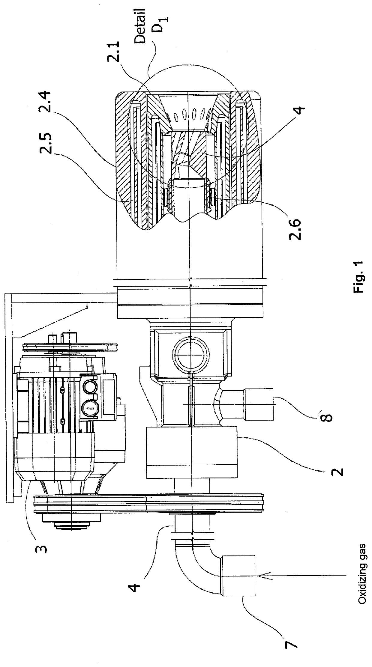
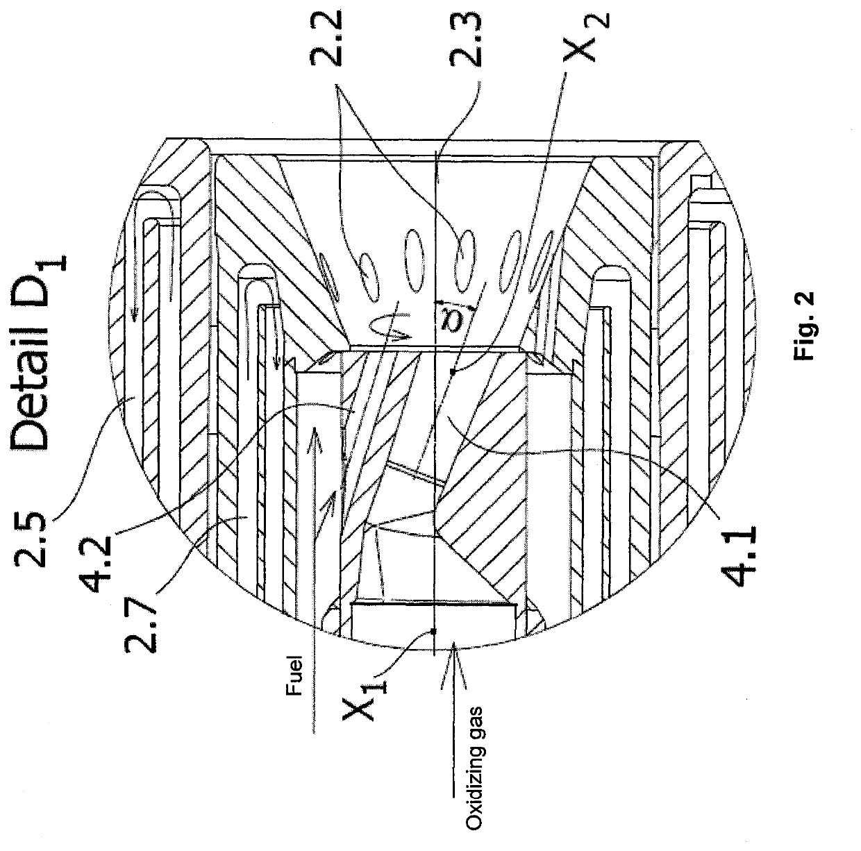
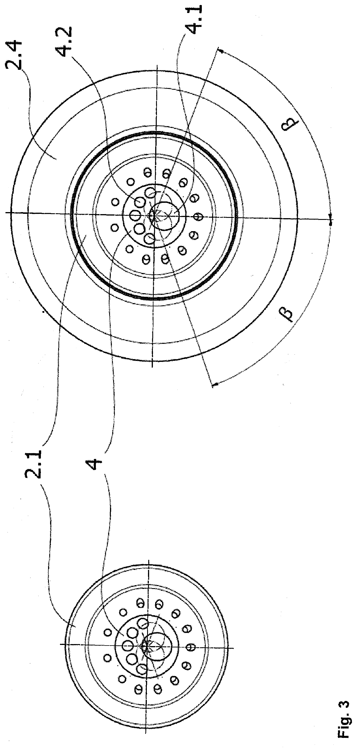
[0015]Combined burner 1 consists of a fixed part 2, whose main part consists of a body 2.1. Movable nozzle 4 is rotatably installed inside the body 2.1. Body 2.1 is provided with protective outer housing 2.4, fixedly connected with wall 5 or cover 6 or the ceiling of the furnace. Outside fixed housing 2.4 is cooled by liquid or gas, which are forced into the channels 2.5, created in the outside housing 2.4. The body 2.1 of the burner is also provided with cooling channels 2.7 for cooling the face of the burner by liquid or gas. Wall 5 of the furnace can consist of cooled panels, or could be made of refractory material. Oxidizing gas is brought to the movable nozzle 4 by the inlet 7 and fuel is brought to the fixed part 2 of the burner by inlet 8. The burner is installed such that the orifice of the burner is in the distance a1 from the wall 5 of the furnace. The distance a1 is chosen so that the jet of gases from the burner doesn't collide with the lining of the furn...


PUM


Abstract

Combined burner for blowing oxidizing gas and fuel into melting furnace, which is fixedly installed into the furnace and provided with outlet apertures for fuel and oxidizing gas, consists, according to this invention, of fixed part (2) of the burner (1) and of a movable nozzle (4), which is rotatably installed inside the body (2.1) of the fixed pan (2) of the burner, supply (7) of the oxidizing gas is connected to the movable nozzle (4) and it is controlled by actuator (3), installed outside of the working space of the furnace, while the axis x2 of the orifice of the movable nozzle (4) is diverted front the rotation axis x1 of the movable nozzle (4) by angle a in the range of 5-60° and the movable nozzle (4) is rotatable around the axis X1 in any direction by angle β in the range of 0-180°. The movable nozzle allows directing blown gases into various places in the furnace. At the same time, the whole burner is fixedly installed in the wall or ceiling, or the cover of the furnace, and the space of the furnace thus remains sealed.

Description

TECHNICAL FIELD[0001]Combined burner for injecting oxidizing gas and fuel is meant for blowing oxygen and fuel during the melting of scrap in melting furnaces.STATE OF THE ART[0002]The burners presently used are at the same time used as nozzles and they are fixedly installed into the walls of the furnace. Injected oxidizing gas, which is oxygen or air enriched by oxygen, and injected fuel—e.g. natural gas, are blown into a given fixed place in the furnace. This means that the axis of blown oxygen and fuel doesn't move. This restricts the efficiency of transferring the heat of the flame into the charge and also the efficiency of the blown oxidizing gas, because the reaction happens in a relatively small volume in the space of the furnace, and heat flux decreases with growing temperature of the charge surface. The difference between the temperature of the heat source, which is the temperature of the burning of fuel and some chemical elements of the charge with oxygen, and the temperat...

Claims


Application Information

Patent Timeline
IPC IPC(8): F23D14/22F23D14/32F27B3/20F27D99/00
CPCF27D99/0033F27B3/205F23D14/22F27D2099/004F23D2900/14481F23D14/32F23D2900/14003F23D14/24F23L2900/07005F23L7/007Y02E20/34
Inventor BRHEL, JAROSLAV
Owner HTT ENG SPOL
Learn More