
Aerofoil structure

a technology of aerofoil and structure, applied in sandwich constructions, transportation and packaging, manufacturing tools, etc., can solve the problems that the benefits of these new materials are currently not being exploited, and achieve the effects of reducing the number of manufactured parts, reducing the size, and efficient structural design

Active Publication Date: 2012-05-31
AIRBUS OPERATIONS LTD
View PDF2 Cites 5 Cited by
  • Summary
  • Abstract
  • Description
  • Claims
  • Application Information

AI Technical Summary

Benefits of technology

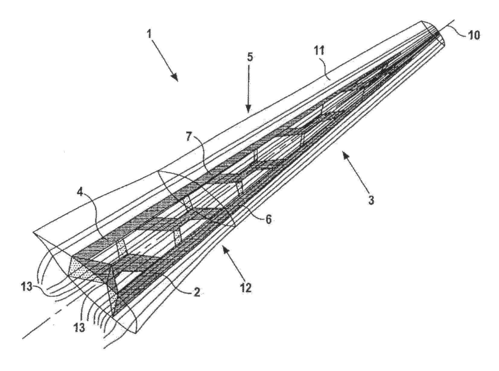
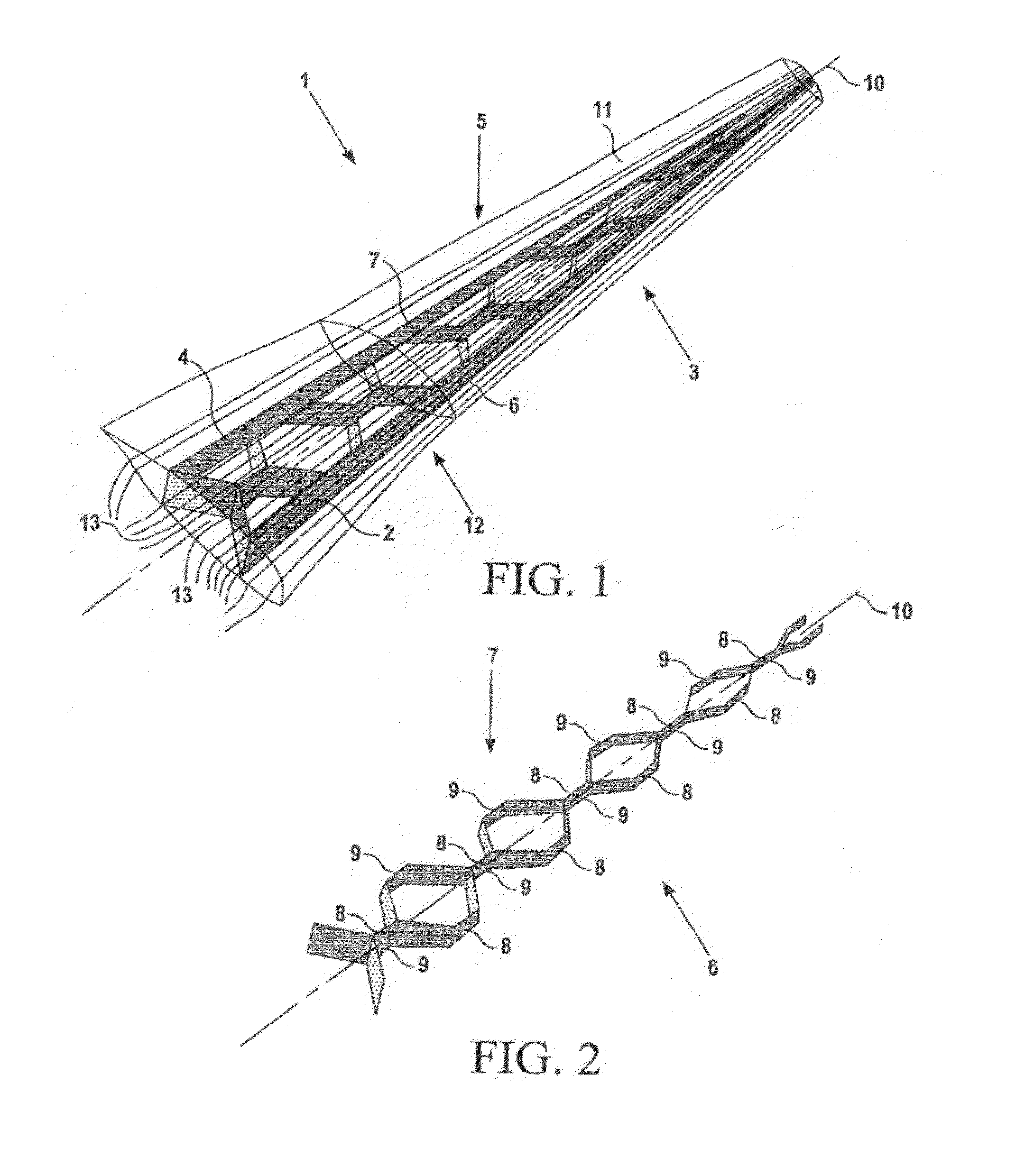
[0006]Loads in a structure always follow straight lines between points. The traditional spar / rib “box” design described above and commonly used in aircraft wings and many other aerofoil structures has no reinforcing members that lie on or close to the torque load lines, which typically lie at around 45 to 60 degrees with respect to the main spar. The torque loading of aerofoil structures having the traditional spar / rib design is therefore mostly supported by the covers. The present invention is advantageous in that portions of each corrugated reinforcing member between its adjacent ridges can more closely follow these torque load lines, leading to a more efficient structural design. Each corrugated reinforcing member is also able to support the aerodynamic loads to maintain the aerofoil cross-section shape, so may partially or fully replace the ribs of the traditional design. Each corrugated reinforcing member is also able to support axial or bending loads, so the stringers of the traditional design may be of a reduced dimension or omitted altogether.

Problems solved by technology

With recent shifts away from metallic aircraft wing design towards composite or plastic structures, some benefits of these new materials are currently not being exploited by following traditional wing designs.

Method used


Image

  • Aerofoil structure
  • Aerofoil structure
  • Aerofoil structure

Examples


Embodiment Construction

[0024]An aircraft wing 1 embodying the present invention is shown in FIG. 1. The wing includes a front spar 2 towards a leading edge 3 and a rear spar 4 towards a trailing edge 5 of the wing 1. A pair of back-to back corrugated reinforcing members 6,7 are disposed between the front 2 and rear 4 spars.

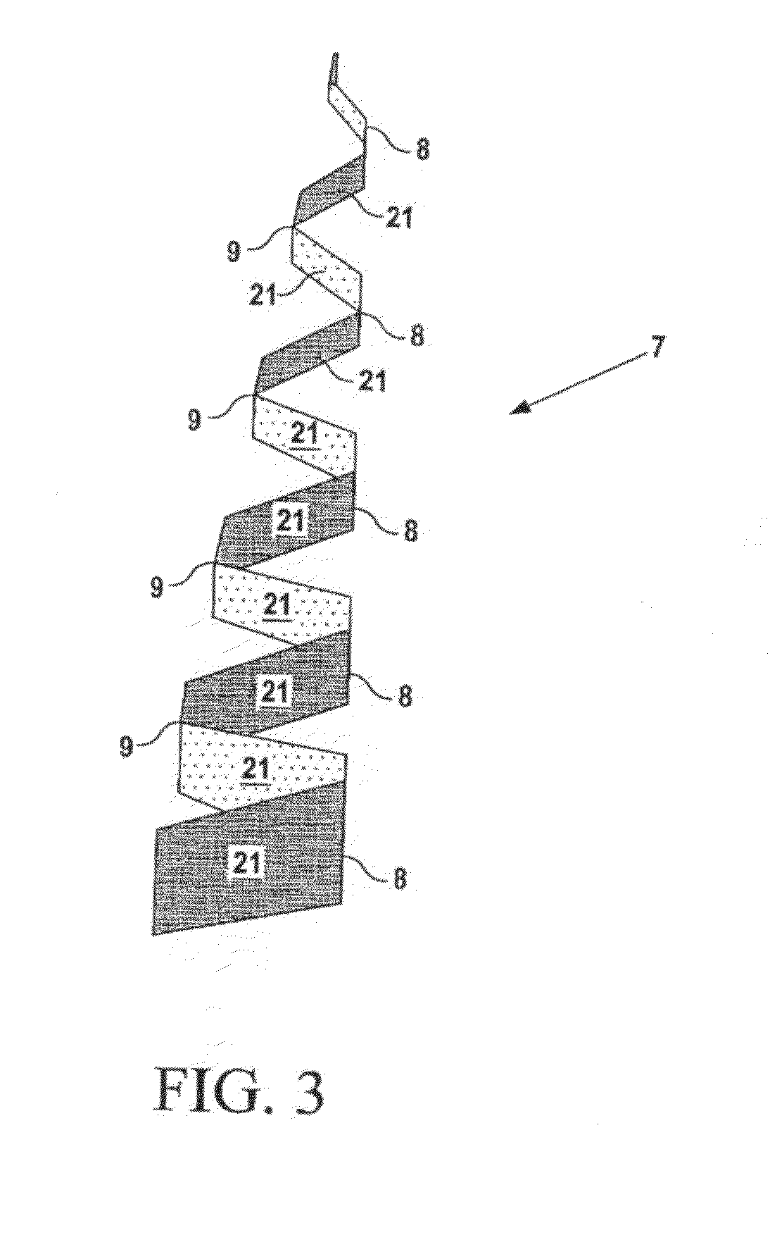
[0025]The pair of back-to-back corrugated reinforcing members 6,7 are shown in isolation in FIG. 2. Each reinforcing member 6,7 has corrugations forming a series of forward ridges 8 and aft ridges 9. The reinforcing members 6,7 are arranged such that respective forward and aft ridges 8,9 thereof sit back-to-back substantially along a longitudinal centre line 10 of the wing 1. The reinforcing members 6,7 are connected to one another where their respective ridges 8,9 meet along the centre line 10.

[0026]The front reinforcing member 6 is arranged such that its forward ridges 8 meet the front spar 2. The rear reinforcing member 7 is arranged such that its aft ridges 9 meet the rear spar 4. T...


PUM

PropertyMeasurementUnit
Lengthaaaaaaaaaa
Structureaaaaaaaaaa
Volumeaaaaaaaaaa

Abstract

An aerofoil structure (1) comprising at least two spars (2, 4) spaced apart in a fore and aft direction so as to define a fuel carrying volume between the spars, and at least one longitudinal corrugated reinforcing member (6, 7) disposed between the spars, each reinforcing member being corrugated in the longitudinal direction to form a series of forward ridges (9) on a forward side of the reinforcing member and a series of aft ridges (8) on an aft side of the reinforcing member, wherein each reinforcing member is directly attached by its forward ridges to one of the spars or to the aft ridges of an adjacent one of the reinforcing members, and wherein each reinforcing member is directly attached by its aft ridges to one of the spars or to the forward ridges of an adjacent one of the reinforcing members. Also, a method of manufacturing an aerofoil structure. The reinforcing member(s) may extend substantially the entire length of the structure to reduce the number of manufactured parts of the structure, increase the stiffness of the structure and reduce the weight of the structure.

Description

FIELD OF THE INVENTION[0001]The present invention relates to an aerofoil structure and a method of manufacturing an aerofoil structure.BACKGROUND OF THE INVENTION[0002]An aerofoil structure is a body, such as an aircraft wing or turbine blade, designed to provide a desired reaction force when in motion relative to a surrounding working medium. Some aerofoil structures, such as aircraft wings and wind turbine blades, generate lift perpendicular to the surrounding airflow. Others, such as racing car wings, generate downforce. Other examples of aerofoil structures include propeller blades, helicopter rotor blades, sailboat centreboards, and aircraft vertical and horizontal tail planes and control surfaces.[0003]Aircraft wings, and many other aerofoil structures, typically comprise a thin outer skin supported by a reinforcing inner framework and are known as a semi-monocoque. The upper and lower skins, or covers, of a wing support the aerodynamic pressure distribution. These aerodynamic...

Claims


Application Information

Patent Timeline
IPC IPC(8): B64C3/20B64C3/34B21D39/03F03D80/00
CPCB64C3/22Y10T29/49622Y10T29/49826
Inventor GROVES, DAVIDPAYNE, CHRISTOPHER
Owner AIRBUS OPERATIONS LTD
Learn More