Control Valve for Pressure Reduction

a technology of control valve and control valve, which is applied in the direction of fluid pressure control, diaphragm valve, instruments, etc., can solve problems such as the affect of product quality or taste, and achieve the effect of reducing the pressure on the product and reducing the mechanical stress

Inactive Publication Date: 2012-05-31
KRONES AG
View PDF9 Cites 2 Cited by
  • Summary
  • Abstract
  • Description
  • Claims
  • Application Information

AI Technical Summary

Benefits of technology

[0004]One aspect of the disclosure is therefore to make a control valve available, which can be employed particularly in the foodstuffs industry for liquids contai

Problems solved by technology

When valves of this nature are employed in food technology for liquid foodstuffs such as soft drinks, teas or juices which include solid constituents, for example fibers, juice sacks or

Method used


Image

  • Control Valve for Pressure Reduction
  • Control Valve for Pressure Reduction

Examples


Embodiment Construction

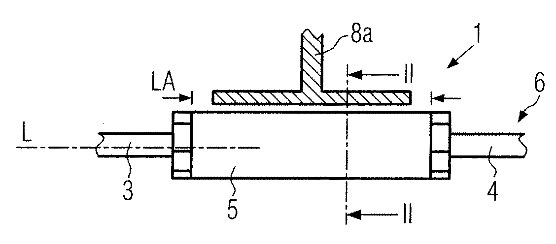
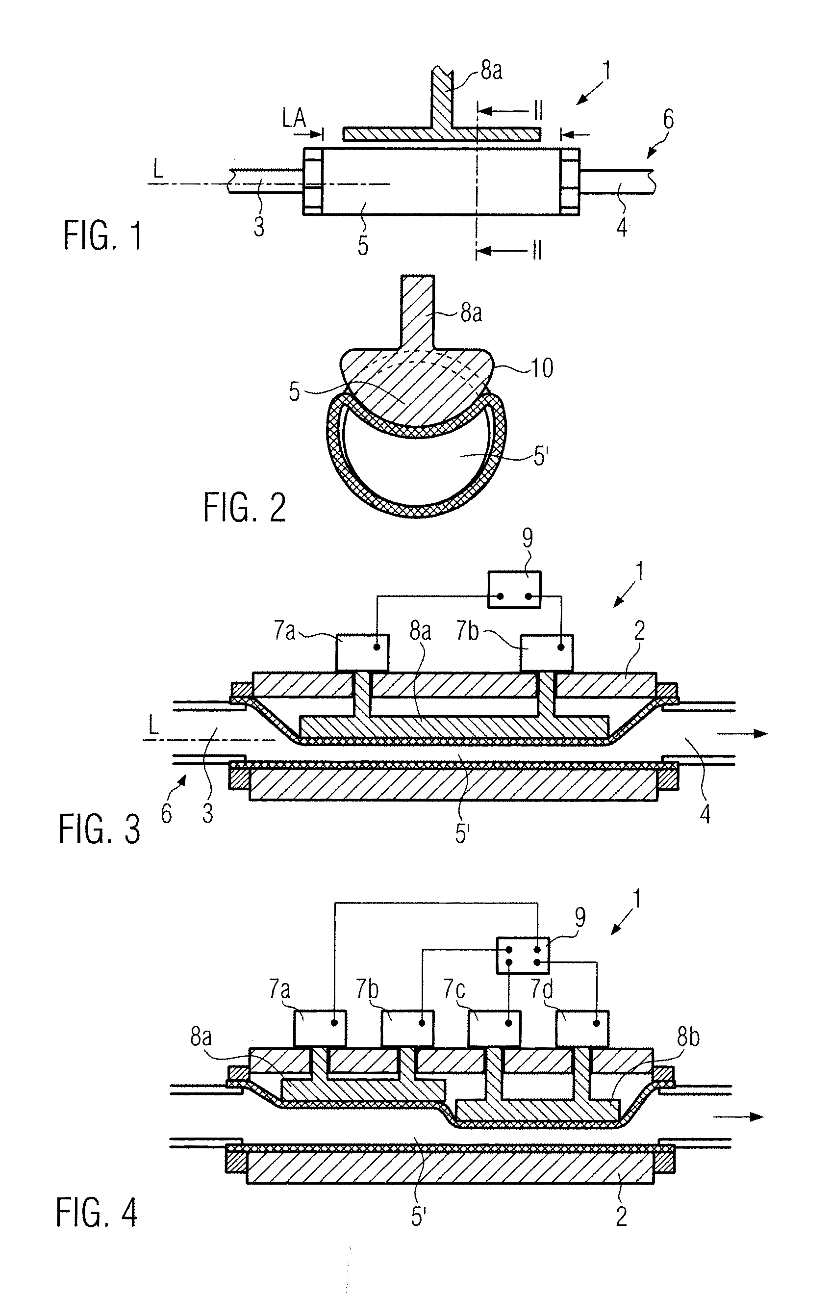
[0022]FIG. 1 shows a control valve 1 according to the disclosure. This control valve 1 has an inlet 3 and an outlet 4 and a channel located between the inlet 3 and outlet 4. The channel is formed as an elastic through-flow channel 5 which is coupled to the normal product line 6. The through-flow channel 5 has a line section LA, consisting of an elastic material, such as for example silicone rubber or PVC, and which is extended in its longitudinal axis L. The elastic through-flow channel 5 can thus be changed over a large line section LA with regard to its free line cross section, in particular however reduced.

[0023]FIG. 2 shows a cross-sectional representation of the elastic line section of the through-flow channel of a control valve according to the disclosure. The circular cross section of the through-flow region can be seen in the reduced (5′) and non-reduced (5) (shaded) states. The reduction in this representation is, for example, provided by a control piston 8a, which has a ro...


PUM


Abstract

A control valve for pressure reduction, in particular for liquids containing solids and having an inlet, an outlet and a channel between the inlet and outlet, wherethe channel is formed as an elastic through-flow channel with a free line cross section which can be reduced along its longitudinal axis over an extended line section.

Description

CROSS-REFERENCE TO RELATED APPLICATION[0001]The present application claims the benefit of priority of German Application No.102010062195.1, filed Nov. 30, 2010. The entire text of the priority application is incorporated herein by reference in its entirety.FIELD OF THE DISCLOSURE[0002]The disclosure relates to a control valve for pressure reduction, in particular for liquids containing solids.BACKGROUND[0003]A control valve of this nature is known, for example, from DE 11 2005 000 683 T5. It comprises two chambers with inlet and outlet and a channel connecting the two chambers, which is closed off by a partition device—here a membrane under pressure from a spring. When the pressure of the product in the inlet is greater than the pressure from the spring, the partition device opens a small gap in the channel and the liquid can flow into the discharge chamber. On flowing through the gap the pressure of the liquid is reduced over a very short distance. When valves of this nature are em...

Claims


Application Information

Patent Timeline
IPC IPC(8): F16K7/04
CPCG05D16/2033F16K7/045
Inventor RICHTER, VOLKERRUNGE, TORSTEN
Owner KRONES AG
Why Eureka
Try Eureka