Manufacturing process of rectangular nanocrystalline spraying magnetic core used in medium-high frequency environment

A manufacturing process and nanocrystalline technology, which is applied in the manufacture of magnetic cores, inductors/transformers/magnets, electrical components, etc., can solve the problems of low effective magnetic permeability, difficult to shape, low resistivity, etc., and achieve high space utilization , low cost and high resistivity

Pending Publication Date: 2021-08-13
青县择明朗熙电子器件有限公司
View PDF8 Cites 1 Cited by
  • Summary
  • Abstract
  • Description
  • Claims
  • Application Information

AI Technical Summary

Problems solved by technology

The current production and application of nanocrystalline magnetic cores are mainly ring-shaped. The production process of the ring-shaped magnetic core is relatively simple and mature, and the performance is excellent, and the production period is short. However, the ring-shaped magnetic core can no longer perfectly adapt to changes in the application environment and customer needs. When When the power of the power transformer reaches an ultra-high power range of several hundred kilowatts or more, due to the requirements of current and installation methods, the magnetic core of the power transformer must be made into a rectangular shape. Therefore, it is urgent to develop special-shaped spraying that can more accurately meet customer needs magnetic core
[0003] At present, the rectangular magnetic cores on the market are mainly made of silicon steel. The silicon steel sheet cores produced by the rolling process have low resistivity and low effective permeability. They are mainly used in low-frequency scenarios such as transformers, reactors, and motors. High-frequency application scenarios There are more stringent requirements on the magnetic permeability and frequency/loss characteristics of the magnetic core. Obviou

Method used


Image

  • Manufacturing process of rectangular nanocrystalline spraying magnetic core used in medium-high frequency environment
  • Manufacturing process of rectangular nanocrystalline spraying magnetic core used in medium-high frequency environment
  • Manufacturing process of rectangular nanocrystalline spraying magnetic core used in medium-high frequency environment

Examples


Embodiment 1

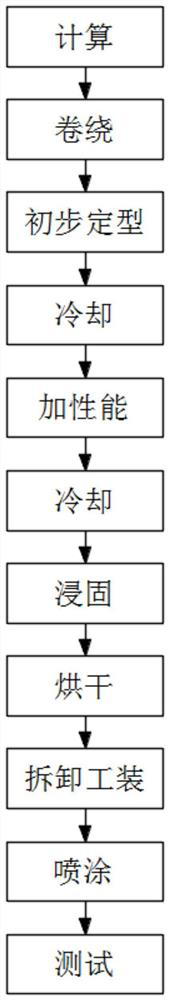
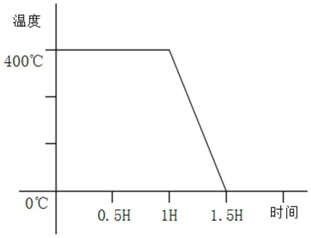
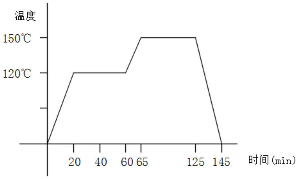
[0046]Calculate the size of the 24*32*38*46*30 rectangular magnetic core converted into a toroidal magnetic core to be 38*44.4*30, and use Keruisi 30mm iron-based nanocrystalline ribbon to wind a 38*44.4*30 on the winding machine The ring magnetic core is put into a custom-made stainless steel fixture, sent into an annealing furnace, the stress is removed to set the shape, the tooling is removed to set the shape, and the stress-relieved magnetic core is sent to the heat treatment furnace to increase performance. After the treatment, it is air-cooled and the magnetic core is restored. After reaching room temperature, soak epoxy resin, rinse off the surface glue, and send it to an annealing furnace to dry the glue. After drying, spray the magnetic core with epoxy paint, and spray 10 times on each side to obtain a sprayed magnetic core.


PUM


Abstract

The invention relates to the technical field of power transformers, and particularly discloses a manufacturing process of a rectangular nanocrystalline spraying magnetic core used in a medium-high frequency environment, which comprises the following specific process steps of 1, calculation, 2, winding, 3, preliminary shaping, 4, cooling: enabling the heated magnetic core to be subjected to air cooling treatment, and removing the tool, 5, performance improvement, 6, cooling: enabling the magnetic core subjected to heat treatment to be subjected to air cooling treatment, 7, soaking and solidifying, 8, drying, 9, removing the tool, 10, spraying, and 11, testing. The rectangular nanocrystalline spraying magnetic core manufactured through the process is not affected by mechanical stress any more, the magnetic performance is stable, medium-high frequency loss under high magnetic induction is low, and the spraying magnetic core has the advantages of being small in size and low in cost.

Description

technical field [0001] The invention relates to the technical field of power transformers, in particular to a manufacturing process for rectangular nanocrystal sprayed magnetic cores suitable for medium and high frequency environments. Background technique [0002] Nowadays, the application of magnetic cores is more and more extensive, the application environment is also more complex, the market demand is more precise, and the needs of customers for the performance and types of magnetic cores are more diverse. Compared with common types of magnetic cores, there are many special-shaped or precise The gap in the magnetic core market with higher precision is waiting for us to fill. The current production and application of nanocrystalline magnetic cores are mainly ring-shaped. The production process of the ring-shaped magnetic core is relatively simple and mature, and the performance is excellent, and the production period is short. However, the ring-shaped magnetic core can no...

Claims


Application Information

Patent Timeline
IPC IPC(8): H01F41/02H01F41/00
CPCH01F41/0213H01F41/005H01F41/02
Inventor 韩飞飞
Owner 青县择明朗熙电子器件有限公司
Why Eureka
Try Eureka