Split-pole magnetic module for electric machine rotors

a technology of electric machine rotors and magnetic modules, which is applied in the direction of magnetic circuit rotating parts, magnetic circuit shape/form/construction, instruments, etc., can solve problems such as inability to achieve, reduce the size and/or mass of the rotor for a permanent magnet machine, and facilitate the insertion of an assembled rotor.

Inactive Publication Date: 2012-05-31
GENERAL ELECTRIC CO
View PDF5 Cites 35 Cited by
  • Summary
  • Abstract
  • Description
  • Claims
  • Application Information

AI Technical Summary

Benefits of technology

[0016]Advantageously, embodiments of the new split-pole magnetic module have magnetic flux that is self-contained within the interior region of the lamination stack (i.e, closest to the rotor yoke). The rotor yoke is thereby free to be optimized for providing structural support of the rotor pole modules; i.e, it is not required to carry magnetic flux. Furthermore, and even more importantly, a simple magnetic keeper is provided in one or more embodiments to contain the magnetic flux entering and exiting the outer surface of each split-pole module, thereby self-containing the magnetic flux within each module/keeper assembly, and permitting the assembly and handling of individual rotor pole modules, as well as the complete rotor, without high magnetic fields or magnetic forces. Use of multiple magnetic keepers facilitates insertion of an assembled rotor, with embodiments of the new split-pole magnetic modules coupled thereto, into a stator. Thus, embo

Problems solved by technology

This was not possible in the pr

Method used


Image

  • Split-pole magnetic module for electric machine rotors
  • Split-pole magnetic module for electric machine rotors
  • Split-pole magnetic module for electric machine rotors

Examples


Embodiment Construction

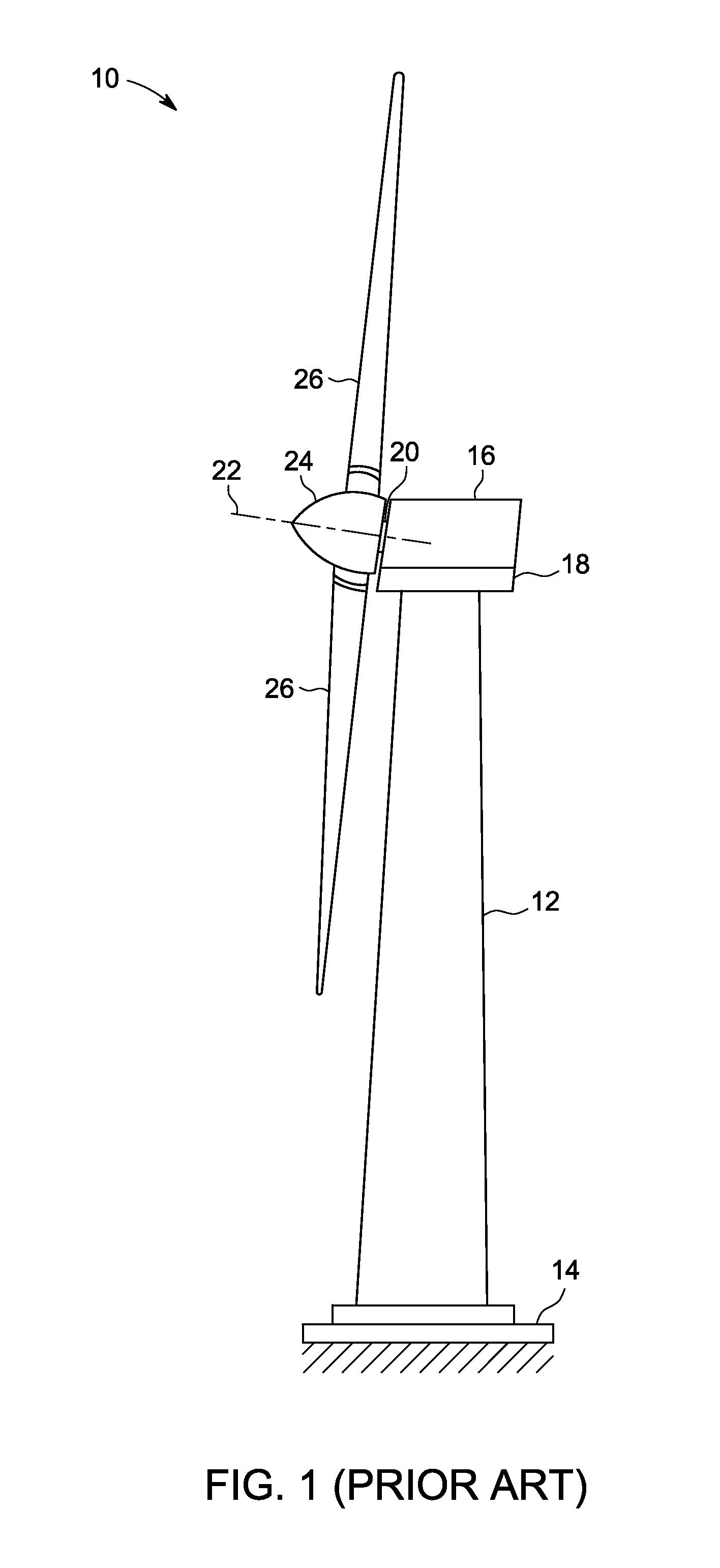
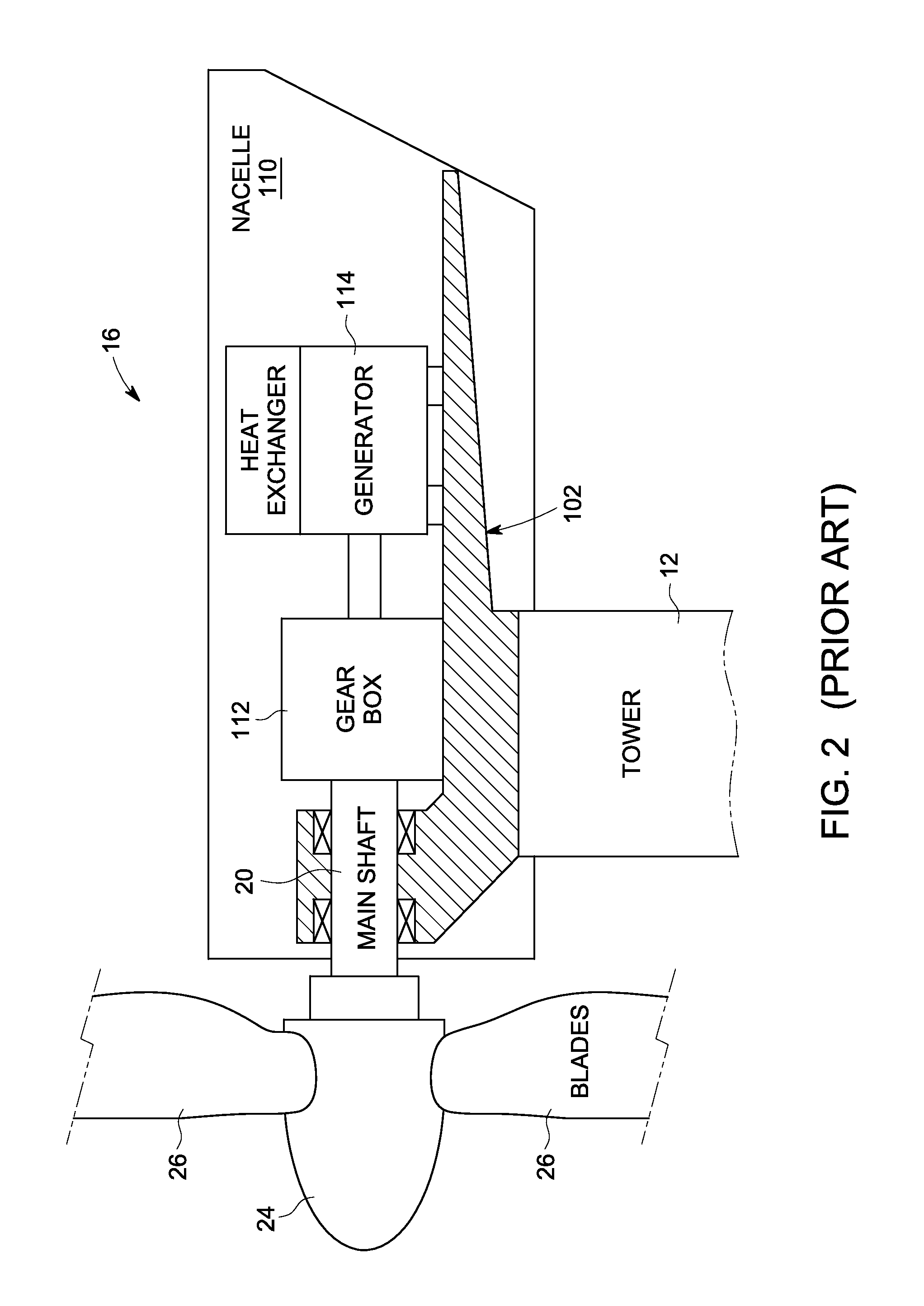
[0038]Embodiments of the invention provide a new split-pole permanent magnet rotor and / or methods of manufacturing and / or assembling the same for use in, or as part of, a large (multi-megawatt) permanent magnet machine. Non-limiting examples of a permanent magnet machine are a permanent magnet generator for a wind turbine, a drive train product for a wind turbine, and an electrical machine for use in other applications, such as power generation and / or vehicle propulsion.

Components, Features and Structure

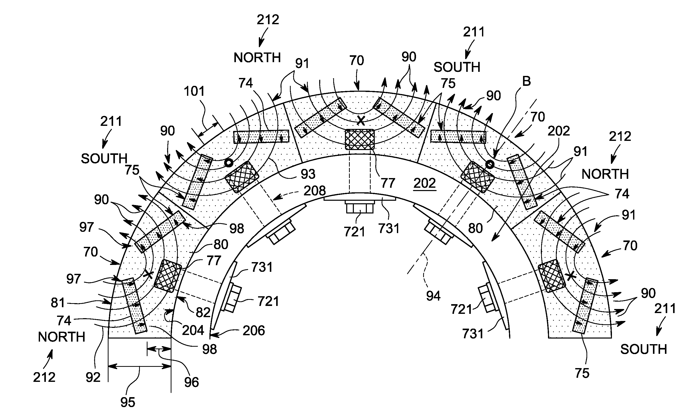
[0039]FIG. 7A is a perspective, exploded-parts view of an embodiment of a new split-pole magnetic module 70 for use as part of a split-pole permanent magnet rotor. FIG. 7B is a perspective top view of the embodiment of the split-pole magnetic module of FIG. 7A, shown assembled. FIG. 7C is a perspective bottom view of the embodiment of the split-pole magnetic module of FIG. 7B, shown assembled. FIG. 8 depicts one-half of an embodiment of a split-pole permanent magnet rotor 200 (herein...


PUM

PropertyMeasurementUnit
Polarityaaaaaaaaaa
Magnetismaaaaaaaaaa
Magnetic fluxaaaaaaaaaa

Abstract

A split-pole magnetic module for use in large permanent magnet machines. The split-pole magnetic module has at least two permanent magnets positioned within a lamination stack at an angle relative to each other so that magnetic flux enters a first portion of an outer surface of the lamination stack and exits a second portion of the outer surface of the lamination stack. Consequently, little if any magnetic flux passes through, or is carried by, the support structure of a rotor or a stator.

Description

CROSS-REFERENCE TO RELATED APPLICATIONSStatement Regarding Federally Sponsored Research or Development[0001]Not ApplicableNAMES OF PARTIES TO A JOINT RESEARCH AGREEMENT[0002]Not ApplicableREFERENCE TO A SEQUENCE LISTING, A TABLE, OR COMPUTER PROGRAM LISTING APPENDIX SUBMITTED ON COMPACT DISC[0003]Not ApplicableBACKGROUND OF THE INVENTION[0004]1. Field of the Invention[0005]The field of the invention relates to power systems generally, and more particularly to certain new and useful advances in permanent magnets motors and generators that can be applied to various applications, such as but not limited to, multi-megawatt wind turbine generators, of which the following is a specification, reference being had to the drawings accompanying and forming a part of the same.[0006]2. Description of Related Art[0007]The assembly of large permanent magnet machines is complicated by the presence of significant magnetic fields and forces. This problem caused some manufacturers to develop expensive...

Claims


Application Information

Patent Timeline
IPC IPC(8): H02K1/28H02K15/16H02K15/00
CPCF03D9/002Y10T29/49004F05B2220/7068H02K1/2766H02K1/30H02K1/32H02K7/1838H02K15/03H02K15/16H02K15/165H02K2213/12Y02E10/722Y02E10/725Y10T29/49009F03D11/0058F03D80/82F03D9/25Y02E10/72
Inventor JANSEN, PATRICK LEE
Owner GENERAL ELECTRIC CO
Why Eureka
Try Eureka