Piezoelectric vibrator element, piezoelectric module, and electronic device

a piezoelectric module and piezoelectric technology, applied in piezoelectric/electrostrictive/magnetostrictive devices, piezoelectric/electrostriction/magnetostriction machines, electrical apparatus, etc., can solve the problems of deteriorating electrical properties and affecting the operation of piezoelectric vibrator elements. , to achieve the effect o

Active Publication Date: 2012-05-31
SEIKO EPSON CORP
View PDF8 Cites 22 Cited by
  • Summary
  • Abstract
  • Description
  • Claims
  • Application Information

AI Technical Summary

Benefits of technology

[0030]With the above configuration, the slit can prevent stress occurring in the mount portion during mounting from propagating in a straight line to the vibrating portion. Thus, the stress from the mount portion propagates to the periphery of the slit and the buffering portion. Furthermore, with the above configuration, since the width of the mount portion is made narrower than the width of the buffering portion by the notches, the path of stress propagating to the positions of the buffering portion corresponding to the periphery of the slit is increased. Accordingly, it is possible to alleviate the stress propagating to the peripheral portion and the vibrating portion. On the other hand, the piezoelectric vibrator element of the abov...

Problems solved by technology

As a result, there is a problem in that stress, namely thermal strain, applied from the bonded portion to a vibrating portion causes an adverse effect on vibration.
Moreover, when the piezoelectric vibrator element is miniaturized, the resonance frequency of the piezoelectric vibrator element may change with time due to the residual stress resulting from the hardened adhesive agent applied to a supporting portion of the piezoelectric vibrator element.
As a result, there is a problem in that the electrical properties of the piezoelectric vibrator element deteriorate considerably.
For example, the impedance may increase and it may be difficult to obtain favorable properties.
However, in recent year...

Method used


Image

  • Piezoelectric vibrator element, piezoelectric module, and electronic device
  • Piezoelectric vibrator element, piezoelectric module, and electronic device
  • Piezoelectric vibrator element, piezoelectric module, and electronic device

Examples


first embodiment

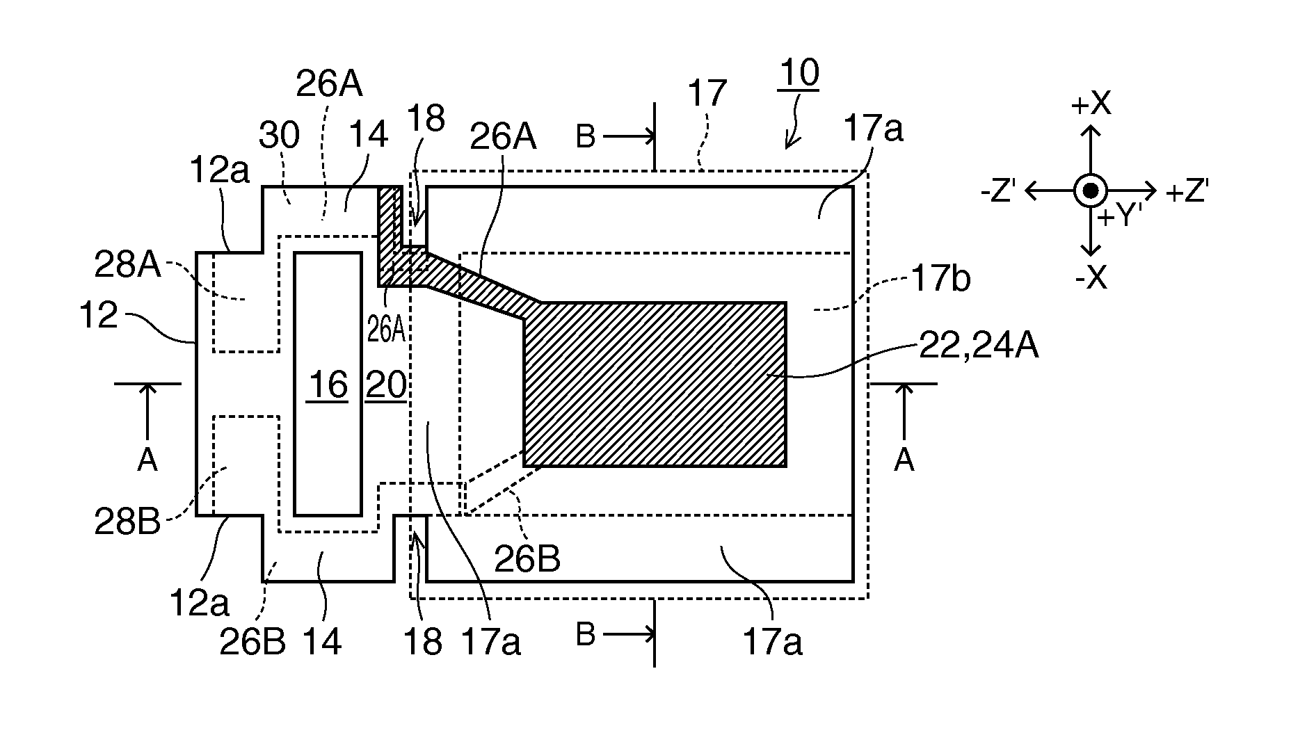
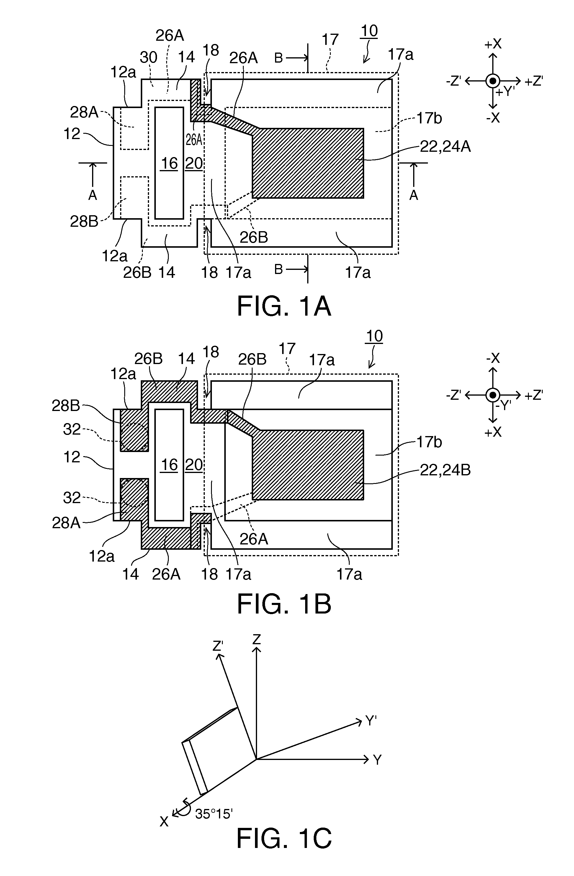
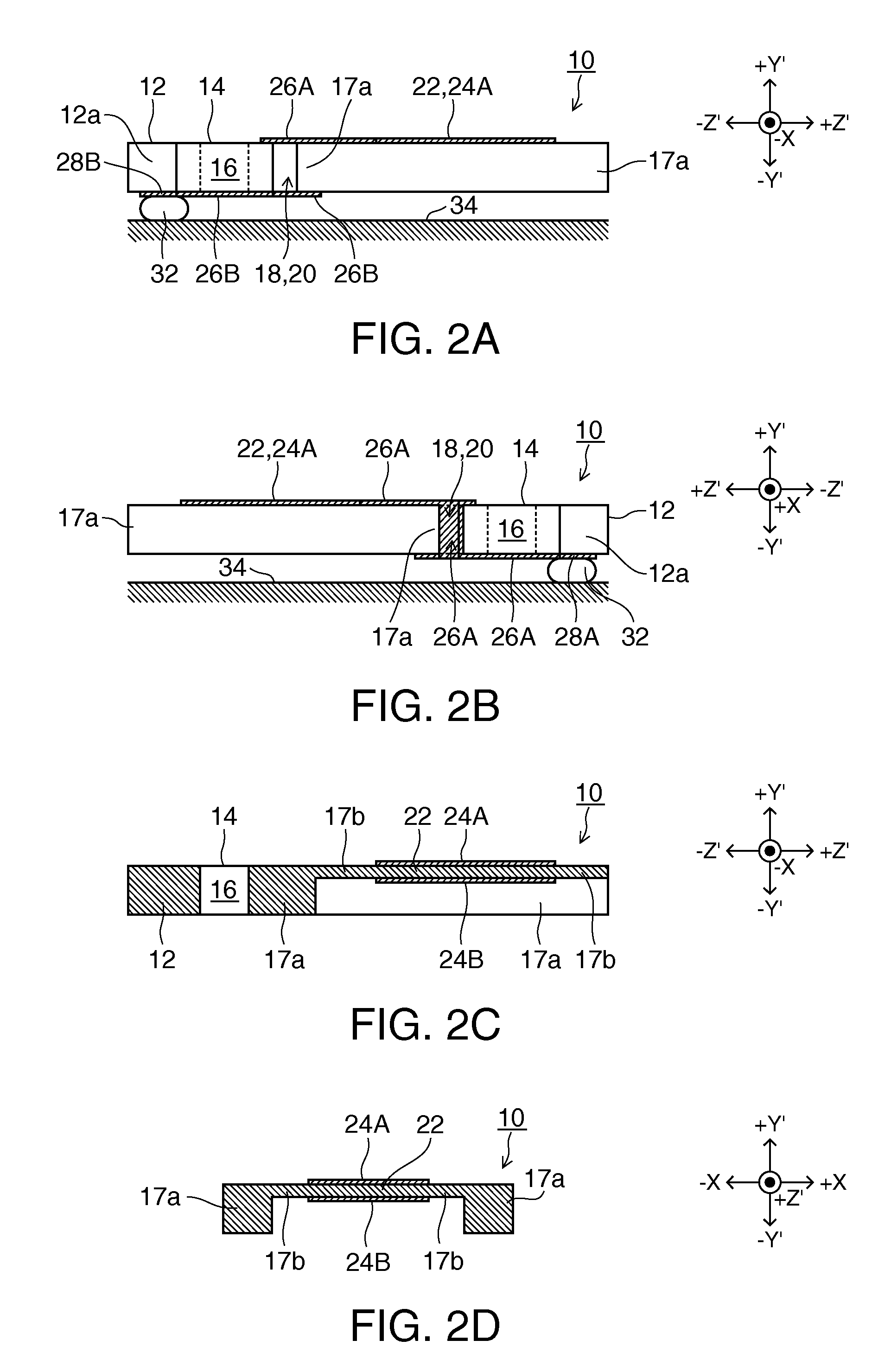
[0057]A piezoelectric vibrator element is shown in FIGS. 1A to 2C. FIG. 1A is a plan view, FIG. 1B is a bottom view, and FIG. 1C is a view showing the cut angle of a quartz crystal substrate. FIG. 2A is a front view, FIG. 2B is a rear view, and FIG. 2C is a cross-sectional view taken along the line A-A in FIG. 1A. A piezoelectric vibrator element 10 according to the present embodiment is formed of an AT-cut quartz crystal substrate in which in an orthogonal coordinate system made up of the crystal axes of a quartz crystal, which are an X axis serving as an electrical axis, a Y axis serving as a mechanical axis, and a Z axis serving as an optical axis, an axis which is the Z axis tilted in a negative (−) Y direction of the Y axis about the X axis is a Z′ axis, and an axis which is the Y axis tilted in a positive (+) Z direction of the Z axis about the X axis is a Y′ axis, the AT-cut quartz crystal substrate being configured by a plane parallel to the X axis and the Z′ axis, and in w...

second embodiment

[0087]FIG. 14 shows an intensity distribution of stress when stress (thermal strain) is applied to a mount portion of the piezoelectric vibrator element according to the present embodiment. The present inventors performed simulation of the intensity distribution of stress when stress is applied to a mount portion of the piezoelectric vibrator element according to the present embodiment. The piezoelectric vibrator element subjected to the simulation has substantially the same shape as the piezoelectric vibrator element of the second embodiment shown in FIGS. 6A to 6D, except that no step is formed between the vibrating portion 22 and the second peripheral portion 62b. Thus, in the description of the present simulation, the constituent elements of the piezoelectric vibrator element 60 shown in FIGS. 6A to 6D will be referenced.

[0088]As shown in FIG. 14, the distribution of stress propagating along the surface of the piezoelectric vibrator element 60 was simulated when an attractive or...


PUM


Abstract

A piezoelectric vibrator element includes a vibrating portion that excites thickness-shear vibration, and a peripheral portion that is disposed on the periphery of the vibrating portion and has a thickness thinner than the vibrating portion, the vibrating portion and the peripheral portion being formed in a piezoelectric substrate. A buffering portion and a mount portion are sequentially connected to the peripheral portion. The buffering portion includes a slit formed between the mount portion and the peripheral portion. The mount portion has notches which are formed at both end portions in a direction orthogonal to an arrangement direction of the mount portion, the buffering portion, and the peripheral portion.

Description

BACKGROUND[0001]1. Technical Field[0002]The present invention relates to a piezoelectric vibrator element and a piezoelectric module using the same. More particularly, the invention relates to a technique of alleviating the effect on a vibrating portion of stress at a mounting position occurring after mounting.[0003]2. Related Art[0004]In the related art, as a method of mounting piezoelectric vibrator elements, there is known a method of applying a conductive adhesive agent to be bonded to a package. Such a method involves a heat treatment process such as drying for hardening the conductive adhesive agent. Thus, due to a difference in the linear expansion coefficients of the piezoelectric vibrator element, the package, and the conductive adhesive agent, strain remains in the bonded portion of the conductive adhesive agent after cooling. As a result, there is a problem in that stress, namely thermal strain, applied from the bonded portion to a vibrating portion causes an adverse effe...

Claims


Application Information

Patent Timeline
IPC IPC(8): H01L41/053
CPCH03H9/02023H03H9/0509H03H9/0519H03H9/02133H03H9/0552H03H9/1021H03H9/19H03H9/0547
Inventor KUSANO, JUN
Owner SEIKO EPSON CORP
Why Eureka
Try Eureka