Ultrasonic diagnostic device

a diagnostic device and ultrasonic technology, applied in tomography, instruments, applications, etc., can solve the problems of difficult to calculate the hardness inside the liver by elastography, difficult to exert compression enough to cause liver displacement, and limited imaging targets, etc., to improve the accuracy of diagnosis. , the effect of improving the transmission sensitivity

Inactive Publication Date: 2012-05-31
HITACHI LTD
View PDF6 Cites 48 Cited by
  • Summary
  • Abstract
  • Description
  • Claims
  • Application Information

AI Technical Summary

Benefits of technology

[0011]According to the present invention, a burst-chirp signal is used to cause interference between the shear waves produced by multiple focused ultrasound waves, thereby allowing a value of amplitude of the shear wave to be magnified. Therefore, this brings about enhancement of the displacement amount (hereinafter, also referred to as transmission sensitivity) of the tissue, with respect to the wave transmission to the tissue. In addition, multiple focused points are provided to disperse energy generated inside the test object, thereby achieving improvement of safety, from the viewpoint of both a thermal mode of action and a mechanical mode of action. Furthermore, transmission with the use of the burst-chirp signal allows expanding of a bandwidth of the switching period, and therefore, it is possible to transmit waves in the switching period that achieves acquisition of high transmission sensitivity at a measurement site, resulting in enhancement of robustness.

Problems solved by technology

In the aforementioned conventional method, there is a problem that a target for imaging is limited to an organ that is located easily compressed from the body surface.
By way of example, there exists a slip surface as an intervening layer between the body surface and the liver, and it is difficult to exert compression sufficient enough to cause displacement in the liver.
Therefore, according to the conventional method, it is difficult to calculate the hardness inside the liver by the use of the elastography technique.

Method used


Image

  • Ultrasonic diagnostic device
  • Ultrasonic diagnostic device
  • Ultrasonic diagnostic device

Examples


first embodiment

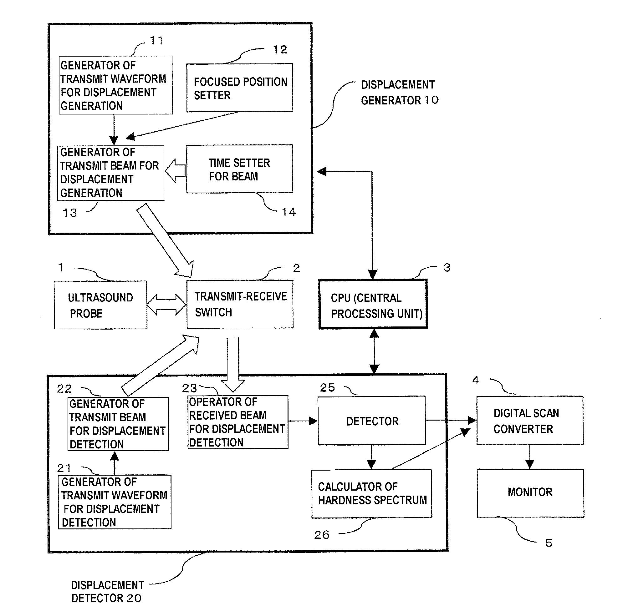
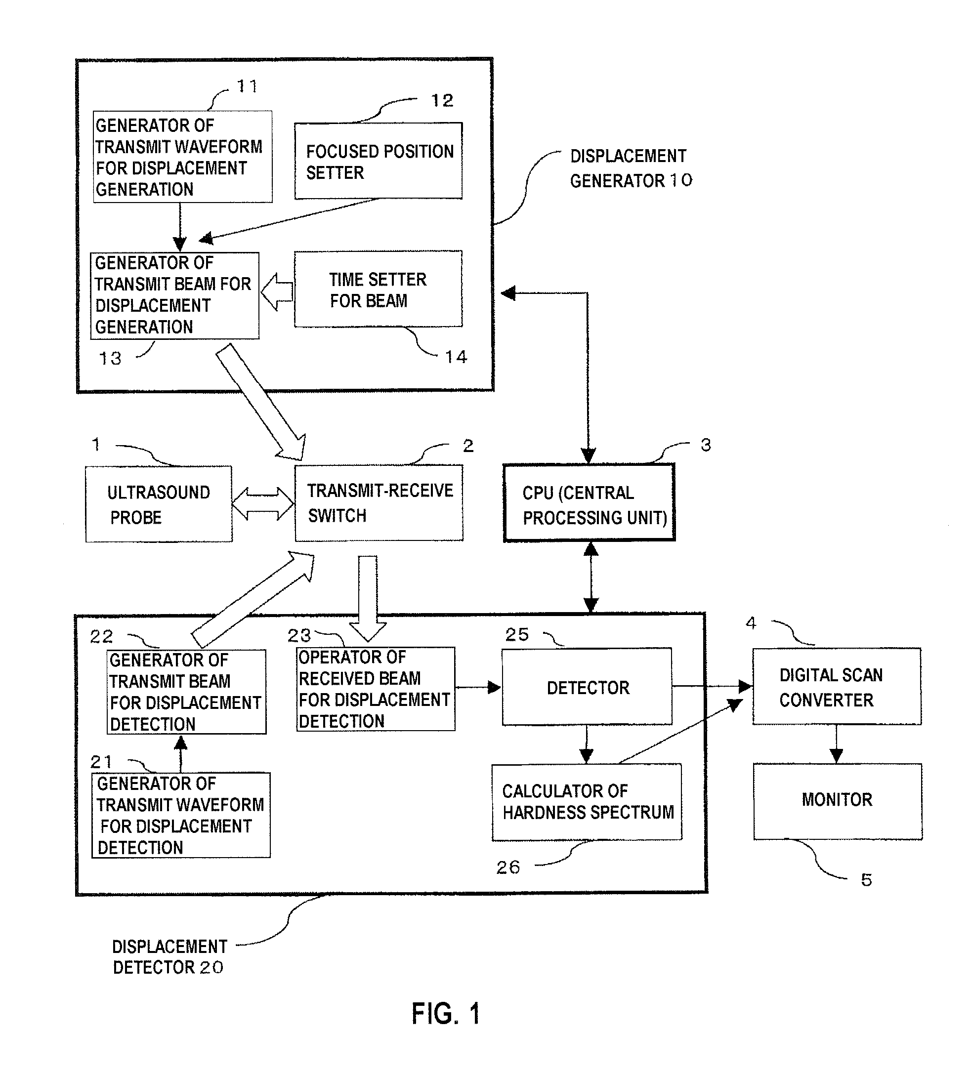
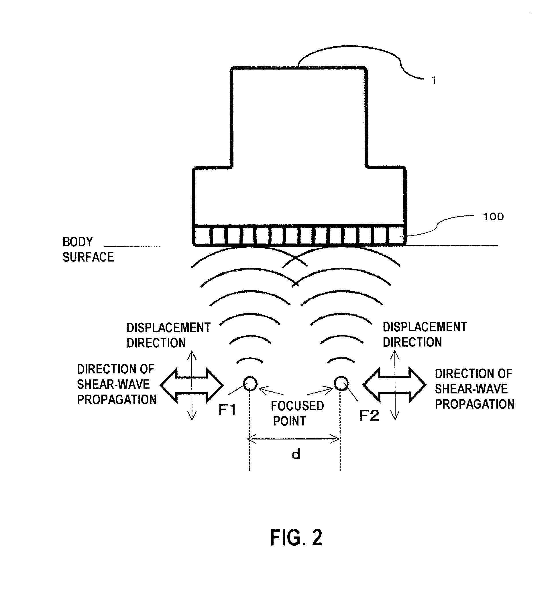
[0040]In the first embodiment, as shown in FIG. 2, an explanation will be made as to the case where a linear array type ultrasound probe 1 is used, being brought into contact with the body surface of a test object, and the ultrasound beam for displacement generation (hereinafter, also described as a focused beam) is focused onto two focused points. The two focused points are respectively positioned on two different rasters (scanning lines) on a target cross-sectional surface within the body, and they are located at the same depth from the body surface. As shown in FIG. 3, a distance between each of the focused points and each device 100 of the ultrasound probe 1 is obtained, and a difference of the distance with respect to each device is divided by a sound velocity of the target object so as to calculate a delay time, and the generator of transmit beam for displacement generation 13 performs transmission of the transmit signal that is provided with the delay time, thereby achieving ...

second embodiment

[0096]In the second embodiment, the switching period of the time duration of beam exposure for exposing one focused point out of the two focused points is kept constant, and only the switching period of the time duration of beam exposure for exposing the other focused point is changed. In other words, this relates to a method for sweeping the phase.

[0097]With reference to FIG. 12, the second embodiment will be explained. As indicated by the sequence of the focused beam shown in FIG. 12, the time width of the focused beam when the focused point F1 is ON and the time width of the focused beam when the focused point F2 is ON are assumed as Ta (fixed). In addition, it is controlled so that a value of the time width Tm from the time when the focused beam directed to the focused point F1 becomes ON to the time when the focused beam directed to the focused point F2 becomes ON is made gradually smaller by a constant interval ΔT, such as from T1(=Tstart=Ta), T2, T3, and so on. With the metho...

third embodiment

[0100]In the present embodiment, an explanation will be made as to the measurement that is conducted with focusing on multiple points, in order to diagnose the hardness on a measurement site two-dimensionally. FIG. 14 illustrates directions of the focused beam exposure when the measurement is conducted at eight focused points F1, F2, F3, F4, F5, F6, F7, and F8 on a concentric circle, and propagation directions of shear waves that are produced along with the exposure. In the present embodiment, the number of the focused points is set to be eight, but the number of the focused points is not limited to this number. FIG. 14(a), (b), and (c) illustrate variations of a pair of two focused points. By way of example, FIG. 14(a) illustrates that neighboring points, that is, the focused point F1 pairs with the focused point F2, the focused point F2 pairs with the focused point F3, the focused point F3 pairs with the focused point F4, and so on. Measurement of those pairs is particularly effec...


PUM


Abstract

In a radiation-pressure elastography technique for transmitting a ultrasound focused beam into a test object body and diagnosing the hardness thereof, it is required to consider high sensitivity and safety.In the present invention, the focused beam is transmitted to two positions as a means for displacing a tissue and exciting a shear wave. In addition, time control is performed in such a manner that a transmit beam serves as a burst-chirp signal, and ultrasound waves are transmitted and received while sweeping a transmit frequency. On this occasion, when the distance between the two focused points and the transmit frequency become integral multiple of the wavelength, two waves interfere with each other, thereby obtaining a large amplitude. Furthermore, when the transmit frequency becomes equal to a resonance frequency peculiar to the tissue, the amplitude also becomes larger. Accordingly, a small intensity of transmit waveform enhances sensitivity. In addition, transmission using the burst-chirp signal facilitates widening of a bandwidth of the transmit frequency, enabling usage of a frequency highly sensitive for a target measurement site. Optional number of focused points and arbitrary positions thereof allow a wide area to be covered.

Description

TECHNICAL FIELD[0001]The present invention relates to an ultrasonic diagnostic device for detecting a difference in hardness inside a test object, by transmitting and receiving ultrasound (ultrasonic) waves.BACKGROUND ART[0002]As a method for diagnosing breast cancer, liver cirrhosis, vascular disorder, and the like, there is a method for diagnosing the hardness inside a test object based on ultrasound echo signals (elastography technique), the method substituting for palpation by a doctor. In the diagnosis of the hardness according to the elastography technique, an engaged person presses a probe against a surface of the test object and exerts compression thereon, thereby causing displacement in tissue inside the living body (hereinafter, this technique is referred to as a conventional method). According to echo signals from the tissue of the living body, before and after compressed by pressure, it is possible to estimate the displacement in the compressed direction and obtain strai...

Claims


Application Information

Patent Timeline
Patent Type & Authority Applications(United States)
IPC IPC(8): A61B8/00
CPCA61B8/08A61B8/14A61B8/4488G01S15/8954G01S7/52026G01S7/52038G01S7/52042A61B8/485
Inventor TABARU, MARIEAZUMA, TAKASHIHASHIBA, KUNIO
Owner HITACHI LTD
Why Eureka
Try Eureka