
Device Comprising A Source For Emitting Ultraviolet Light

a technology of ultraviolet light and source, applied in the direction of material analysis using wave/particle radiation, instruments, nuclear engineering, etc., can solve the problems of only useful application of mixing elements, unwanted high pressure drop, so-called short cuts, etc., to achieve less short cuts, not expensive, and easy to manufacture

Inactive Publication Date: 2012-06-07
SHANGHAI SHUI HU DUN HEALTH TECH CO LTD
View PDF6 Cites 7 Cited by
  • Summary
  • Abstract
  • Description
  • Claims
  • Application Information

AI Technical Summary

Benefits of technology

[0008]It is an object of the present invention to provide a solution to the above-sketched problem. In particular, it is an object of the present invention to provide a device comprising an ultraviolet source and means for controlling the flow of fluid through the device, such that there are less short-cuts or even no short-cuts at all, wherein such means are easy to manufacture and not expensive.
[0015]On the basis of the presence of a plurality of fluid passages, the flow straightening element of the device according to the present invention has a porous structure, so that pressure losses of fluid flowing through the element are low. Another advantage of an application of the flow straightening element is that an influence of variations in inlet conditions can be minimized. Local high velocities prevailing in a flow of fluid can be dampened. The flow straightening element may be installed upstream and / or downstream of the ultraviolet source, so that the irradiance level of the source does not have to be affected. All in all, a very compact, cost-effective flow straightening element can be realized.
[0018]Also in case the lamp is not extending through the flow straightening elements, it is advantageous to have means for covering a central portion of another side of the flow straightening element than the side that is facing the irradiated section. The reason for having such means is that in the central area of the flow straightening element, transmission of ultraviolet light is highest, due to light beams entering the flow straightening element at relatively large reflection angles in the central area. Using means for covering the central portion avoid the transmittance of too much ultraviolet light to the area that is shielded from the ultraviolet light by the flow straightening element. Moreover, at the water inlet side, assuming that the device has a central water inlet, the means may have an additional function in reducing the impact of a jet coming from the central inlet and enhancing distribution of the flow of water over the whole inlet surface of the irradiated section. The means as mentioned comprise a metal plate, for example, which has a closed central portion and a number of spokes extending from the central portion. For sake of completeness, it is noted that it is also possible to have means for covering a central portion of the side of the flow straightening element that is facing the irradiated section.
[0019]Due to the application of flow straightening elements as shielding elements at both ends of the lamp, it is achieved that other sections than the irradiated sections cannot be reached by the ultraviolet light that is emitted by the lamp during operation. The flow straightening elements block the ultraviolet light, and therefore, it is possible to use any desirable type of seals, bearings and construction materials, which may be less resistant to ultraviolet light, and which may therefore be relatively cheap. Furthermore, the flow straightening elements allow the water to pass, wherein there is a straightening effect on the flow of water, while disturbance of the flow pattern does not occur. Pressure losses are low, while an optimal dose output can be achieved. All in all, the flow straightening elements are capable of providing for optimal shielding and various advantageous influences on the flow of water at the same time. When a flow straightening element is used at the water inlet side, velocity variations at the inlet are very effectively damped out. In order to have a flow of water that is even further optimized, the device according to the present invention may be equipped with means for diverging a flow of fluid, which means are arranged at a position between the water inlet and a flow straightening element arranged at the water inlet side, and / or means for converging a flow of fluid, which means are arranged at a position between the water outlet and a flow straightening element arranged at the water outlet side.

Problems solved by technology

Thus, applying a mixing element is only useful when the gain in dose level as a result of an improved flow profile overcomes the losses as a result of a lower irradiance level.
Adding a mixing element may lead to unwanted high pressure drops.
Another problem that is encountered in the field of water disinfecting devices is that so-called short-cuts may be present.
Short-cuts are generally caused by certain inflow conditions and / or inappropriate mixing.

Method used


Image

  • Device Comprising A Source For Emitting Ultraviolet Light
  • Device Comprising A Source For Emitting Ultraviolet Light
  • Device Comprising A Source For Emitting Ultraviolet Light

Examples


Embodiment Construction

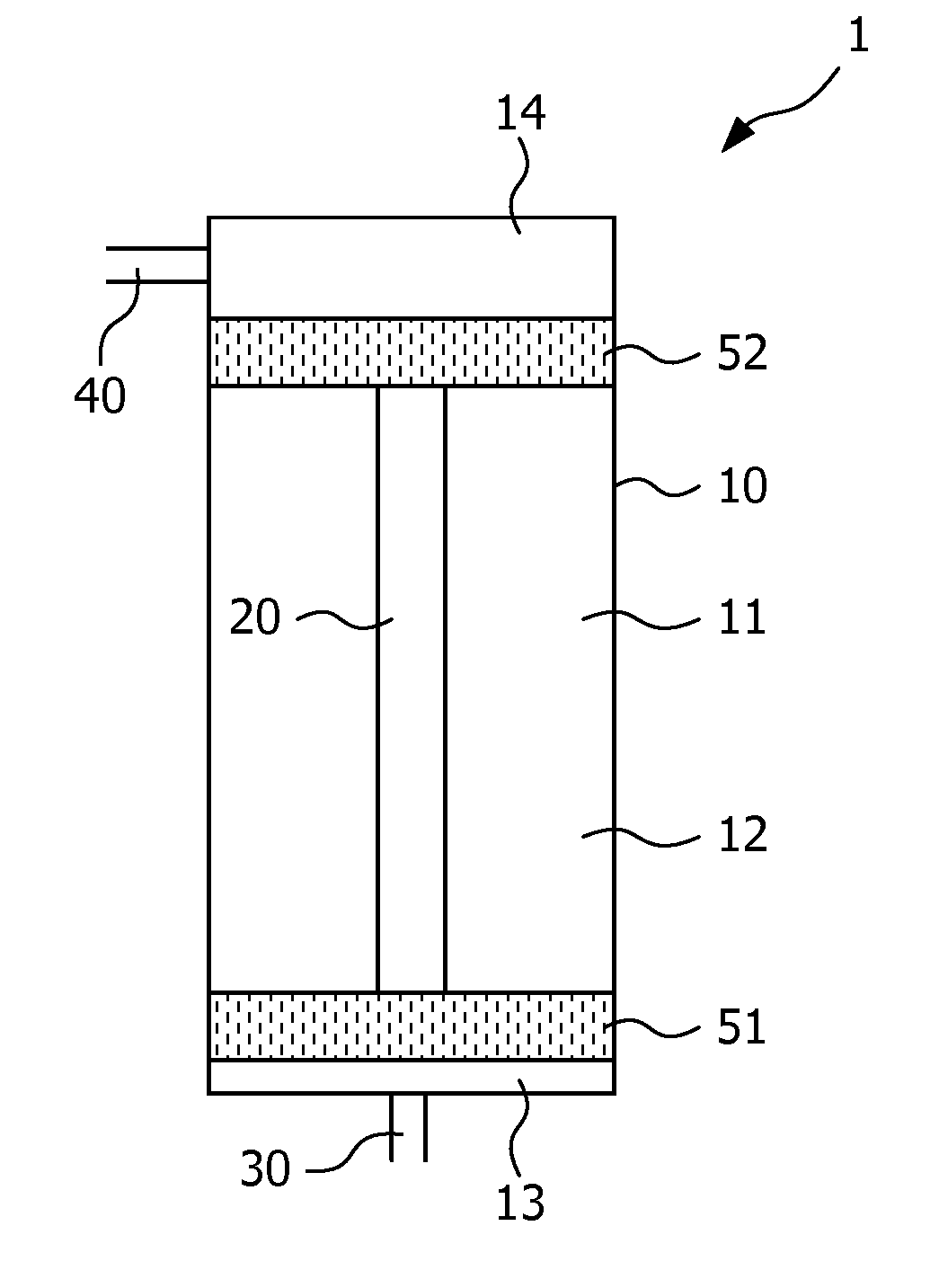
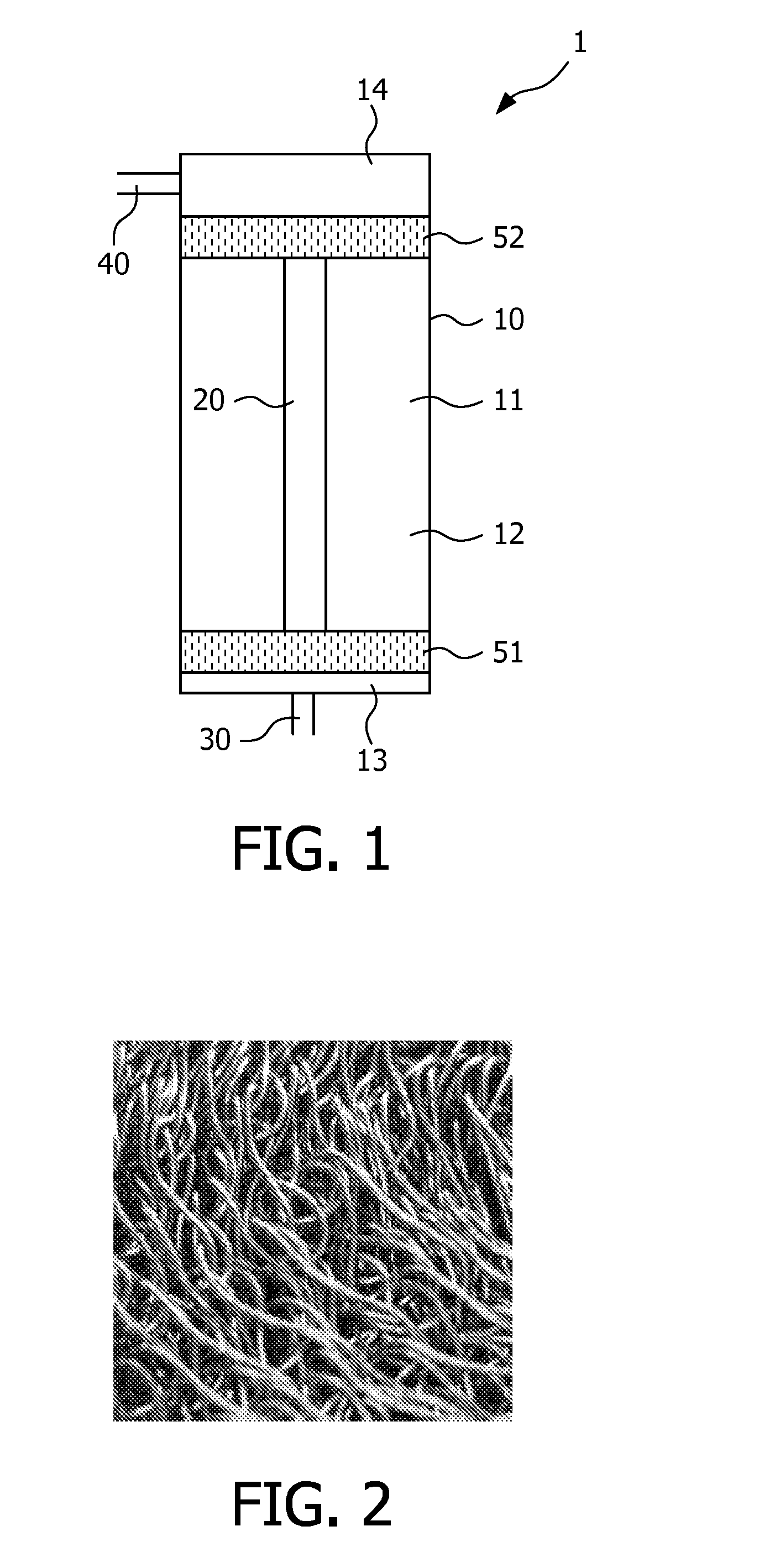
[0030]FIG. 1 shows a first embodiment 1 of a water disinfecting device according to the present invention. The water disinfecting device 1 comprises the following components: a housing 10; a source 20 for emitting ultraviolet light, which is an ultraviolet lamp 20 in this example, and which is arranged in an interior space 11 of the housing; an inlet 30 for letting in water to be treated by means of ultraviolet radiation to the interior space 11 of the housing 10; an outlet 40 for letting out water from the housing 10; and two flow straightening elements 51, 52, wherein one flow straightening element 51, which will hereinafter be referred to as inlet flow straightening element 51, is arranged at an inlet side of the water disinfecting device 1, i.e. at a position near the inlet 30, and wherein another flow straightening element 52, which will hereinafter be referred to as outlet flow straightening element 52, is arranged at an outlet side of the device 1, i.e. at a position near the...


PUM


Abstract

A device (1) comprises a source (20) for emitting ultraviolet light, an inlet (30) for letting in fluid to the device (1), an outlet (40) for letting out fluid from the device (1), and means (51, 52) for performing a straightening action of a flow of fluid through the device (1). The flow straightening means comprise at least one flow straightening element (51, 52) having inlet openings for letting in fluid at one side and outlet openings for letting out fluid at another side, wherein each inlet opening is in communication with a plurality of outlet openings, and wherein the element (51, 52) comprises a maze of randomly arranged, interconnected holes. In such a structure, a water element that is moving from one side of the element (51, 52) to another side may take one of various paths, as a result of which variations in inlet conditions can be dampened.

Description

FIELD OF THE INVENTION[0001]The present invention relates to a device, comprising a source for emitting ultraviolet light, an inlet for letting in fluid to the device, an outlet for letting out fluid from the device, and means for performing a straightening action on a flow of fluid through the device, wherein the flow straightening means are arranged in a fluid path from the inlet to the outlet.BACKGROUND OF THE INVENTION[0002]A well-known example of a device as defined in the preceding paragraph is a device for disinfecting water, in which the element which is arranged inside the housing is a source such as a lamp for emitting ultraviolet light, in particular of the type commonly referred to as UV-C. Exposing infected water to the ultraviolet light has a purifying effect on the water on the basis of the fact that the UV-C light is capable of sterilizing germs. For domestic applications, the ultraviolet source is usually enclosed in a non-opaque holding structure, enabling the desi...

Claims


Application Information

Patent Timeline
Patent Type & Authority Applications(United States)
IPC IPC(8): G21K5/00
CPCA61L2/10C02F1/325C02F2301/022C02F2201/3228C02F2201/328C02F2201/3223
Inventor DUINEVELD, PAULUS CORNELISMONDT, EVATAEKEMA, HARKO JANWIJMA, WILLEM SJOUKEPASTOORS, MARC ALEXANDERBRUGGINK, WILHELMUS HENDRIKUS MARIA
Owner SHANGHAI SHUI HU DUN HEALTH TECH CO LTD
Learn More