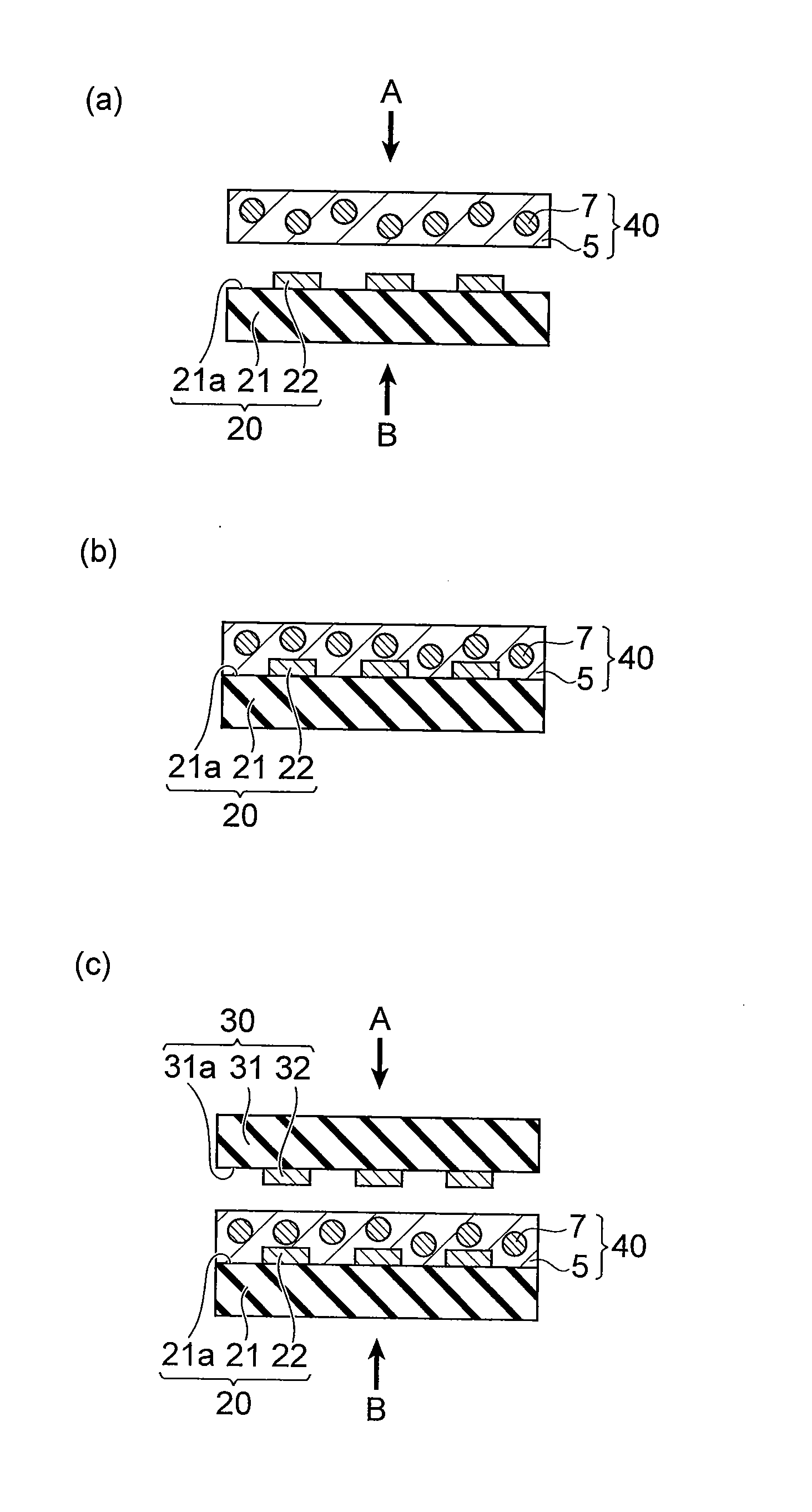
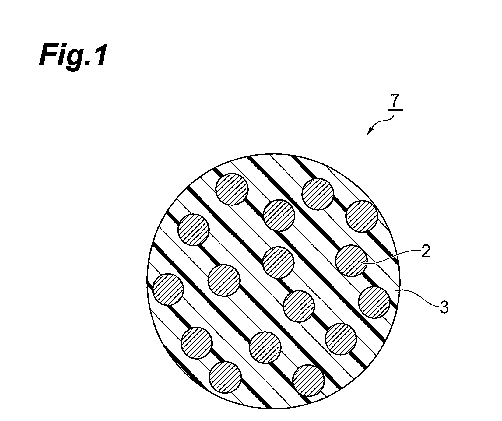
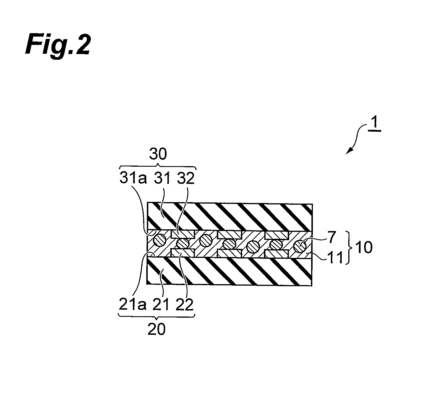
Circuit connecting material, film-like circuit connecting material using the circuit connecting material, structure for connecting circuit member, and method for connecting circuit member

Inactive Publication Date: 2012-06-07
HITACHI CHEM CO LTD
View PDF0 Cites 24 Cited by
  • Summary
  • Abstract
  • Description
  • Claims
  • Application Information

AI Technical Summary

Benefits of technology

[0039]According to the invention, it is possible to provide a circuit connecting material can both ensure insulation between adjacent circuits of a high-definition circuit and ensure conductivity between opposing circuits, as well as a film-like circuit connecting material using it. According to the invention it is also possible to provide a structure for connecting

Problems solved by technology

However, when such circuit connecting materials are used for connection in high-density circ

Method used


Image

  • Circuit connecting material, film-like circuit connecting material using the circuit connecting material, structure for connecting circuit member, and method for connecting circuit member
  • Circuit connecting material, film-like circuit connecting material using the circuit connecting material, structure for connecting circuit member, and method for connecting circuit member
  • Circuit connecting material, film-like circuit connecting material using the circuit connecting material, structure for connecting circuit member, and method for connecting circuit member

Examples


Example

Production Example 1

Preparation of Anisotropic Conductive Particles 1

[Preparation of Conductive Fine Particles]

[0154]Scaly silver powder 1 having a particle size distribution of 0.005-10 μm was obtained by a chemical reduction method. The obtained silver powder 1 was classified to obtain scaly silver powder 2 having a mean particle size of 0.25 μm and a maximum particle size of 0.4 μm.

[Preparation of Anisotropic Conductive Particles]

[0155]The starting monomer for an organic insulating material was prepared by mixing 60 parts by mass of tetramethylolmethane triacrylate, 20 parts by mass of divinylbenzene and 20 parts by mass of acrylonitrile. Also, silver powder 2 was added at 120 parts by volume to 100 parts by volume of the starting monomer for the organic insulating material, and a bead mill was used for dispersion of the silver powder for 48 hours. After mixing 2 parts by mass of benzoyl peroxide with the silver powder-dispersed composition, the mixture was loaded into 850 parts ...

Example

Production Example 2

Preparation of Anisotropic Conductive Particles 2

[0156]The silver powder 2 prepared in Production Example 1 was impregnated with a solution of 3 parts by mass of N-(2-aminoethyl)-3-aminopropyltrimethoxysilane in 100 parts by mass of methyl ethyl ketone, and stirring was carried out for one day and night for hydrophobic treatment of the silver powder surface. Anisotropic conductive particles 2 were obtained in the same manner as Production Example 1, except for using this silver powder with a hydrophobic-treated surface.

Example

Production Example 3

Preparation of Anisotropic Conductive Particles 3

[0157]The anisotropic conductive particles prepared in Production Example 1 were classified to obtain anisotropic conductive particles 3 having a mean particle size of 0.5 μm.


PUM

PropertyMeasurementUnit
Fractionaaaaaaaaaa
Percent by volumeaaaaaaaaaa
Particle sizeaaaaaaaaaa

Abstract

The circuit connecting material of the invention is situated between mutually opposing circuit electrodes, and provides electrical connection between the electrodes in the pressing direction when the mutually opposing circuit electrodes are pressed, the circuit connecting material comprising anisotropic conductive particles wherein conductive fine particles are dispersed in an organic insulating material.

Description

[0001]This is a National Phase Application in the United States of International Patent Application No. PCT / JP2010 / 057165 filed Apr. 22, 2010, which claims priority on Japanese Patent Application No. P2009-109102, filed Apr. 28, 2009. The entire disclosures of the above patent applications are hereby incorporated by reference.TECHNICAL FIELD[0002]The present invention relates to a circuit connecting material, a film-like circuit connecting material using it, a structure for connecting a circuit member and a method for connecting a circuit member.BACKGROUND ART[0003]Circuit connecting materials comprising anisotropic conductive adhesives, in which conductive particles are dispersed in an adhesive, have conventionally been used for connection between liquid crystal displays and TCPs (Tape Carrier Packages), connection between FPCs (Flexible Printed Circuits) and TCPs, and connection between FPCs and printed circuit boards. Recently, flip-chip mounting, for direct mounting of semicondu...

Claims


Application Information

Patent Timeline
IPC IPC(8): H01B1/22H01B1/24H01R43/00H01B1/20B82Y30/00
CPCB82Y10/00H05K3/323H05K3/361H05K2201/0224Y10T29/532H05K2201/0323H01L2224/83101Y10T29/49117H05K2201/026H01L2924/12044H01L2924/00C09D5/00H01R11/01H05K1/14H05K3/32
Inventor ARIFUKU, MOTOHIROKOBAYASHI, KOUJIFUJINAWA, TOHRU
Owner HITACHI CHEM CO LTD
Why Eureka
Try Eureka