Data Sensor Coordination Using Time Synchronization in a Multi-Bus Controller Area Network System

a data sensor and multi-bus technology, applied in the field of vehicle controller area network systems, can solve the problems of mismatching timed data during data integration process, unsynchronized local clocks of the ecus of different can buses, and out of synchronized data being integrated together

Active Publication Date: 2012-06-07
GM GLOBAL TECH OPERATIONS LLC
View PDF4 Cites 66 Cited by
  • Summary
  • Abstract
  • Description
  • Claims
  • Application Information

AI Technical Summary

Benefits of technology

[0005]An advantage of an embodiment is the synchronization of local clocks in an asynchronous controller area network having a plurality controller area network buses which allows the coordination of data from various sensors within a controller area network system. The delays associated with messages transmitted within each controller area network bus in the system are estimated and a global time is adjusted for each controller area network bus to account for the delays. Messages that include the adjusted global time for each respective controller area network bus are transmitted to the various devices to adjust and synchronize local clocks.

Problems solved by technology

Due to the delay in transmitting information in the recessive bits, data sharing and integration of data between two ECUs of different CAN buses in a multi-CAN bus architecture may result in out of synchronized data being integrated together if their clocks are not synchronized.
ECUs utilize their local clocks to time-stamp data, and if the local clocks are not synchronized, then a mismatch of timed data may occur during data integration process.
A vehicle could use an internal clock in attempts to synchronize the time of all the ECU's by sending out a clock signal; however, due to the asynchronous nature of the CAN system and delays that result in transmitting messages across different CAN buses, a message containing a clock signal may be delayed as well in getting to the ECU's which would result in the local clocks of the ECUs of different CAN buses being unsynchronized.

Method used


Image

  • Data Sensor Coordination Using Time Synchronization in a Multi-Bus Controller Area Network System
  • Data Sensor Coordination Using Time Synchronization in a Multi-Bus Controller Area Network System
  • Data Sensor Coordination Using Time Synchronization in a Multi-Bus Controller Area Network System

Examples


Embodiment Construction

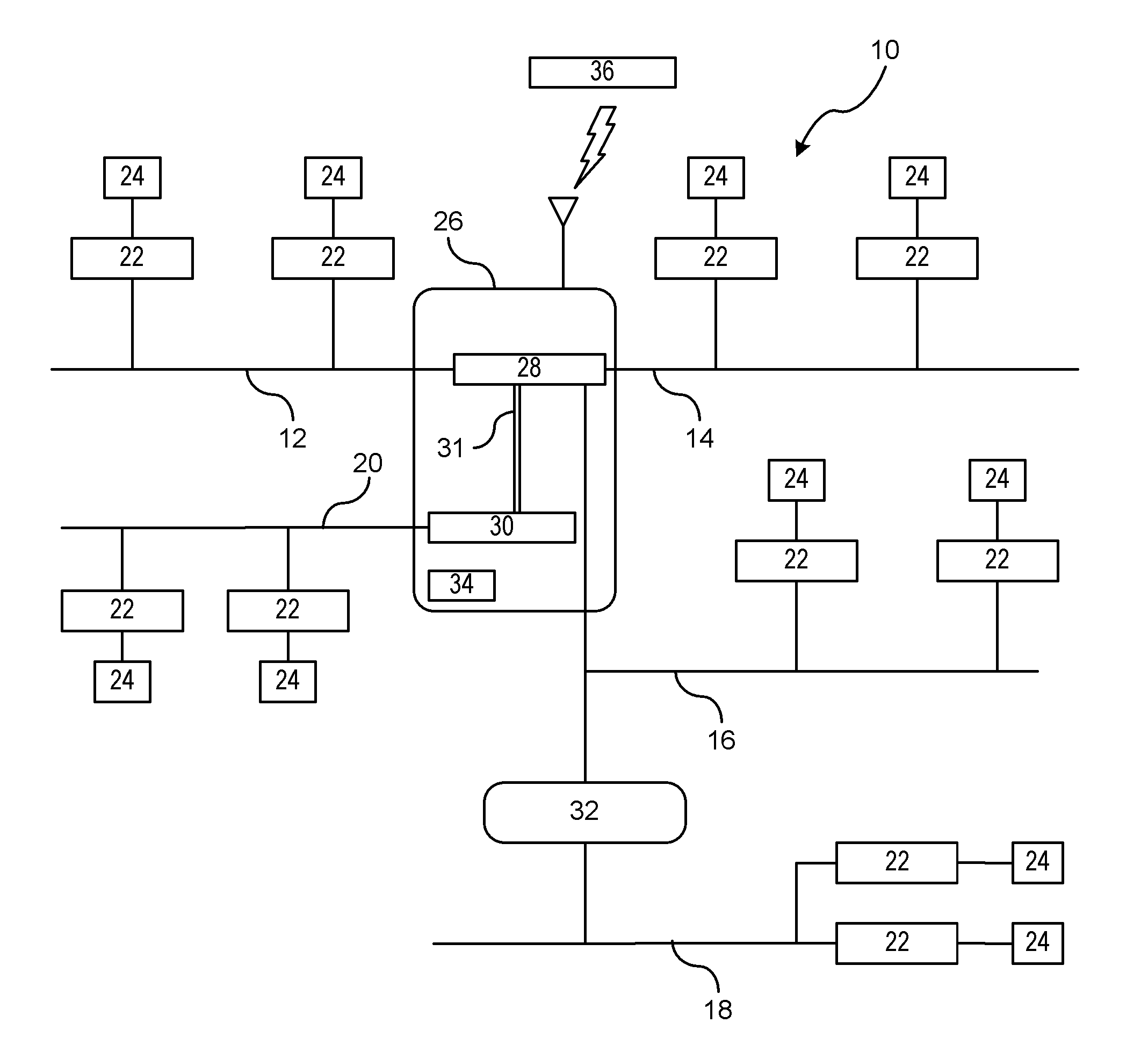
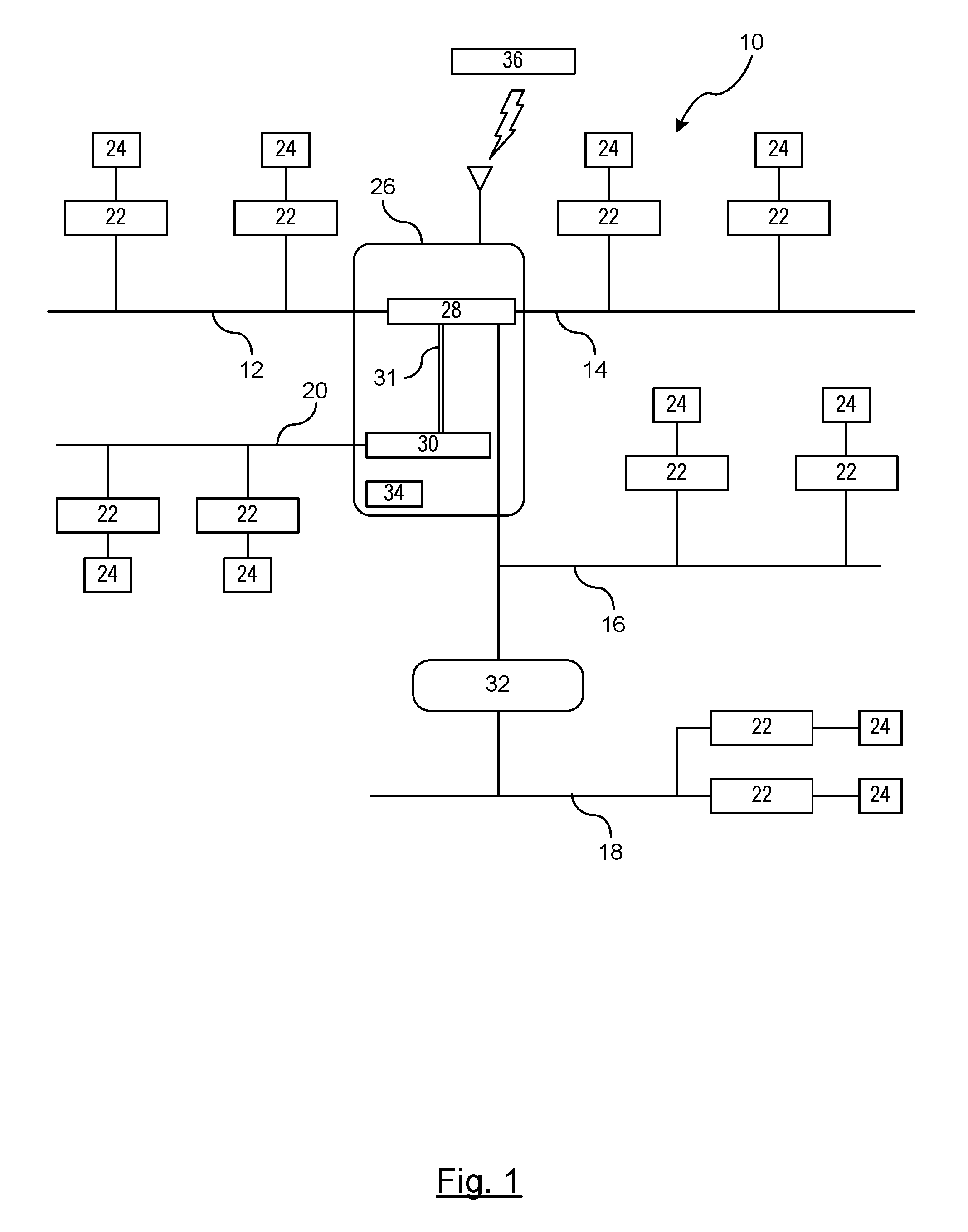
[0011]There is shown in FIG. 1 an architectural block diagram of a vehicular controller area network (CAN) system 10 for synchronizing local clocks of electronic control units coupled to the network. The CAN system 10 includes a plurality of CAN buses, such as a first CAN bus 12, a second CAN bus 14, a third CAN bus 16, a fourth CAN bus 18, and a fifth CAN bus 20. It should be understood that the CAN system 10 may include more or less CAN buses than shown.

[0012]Each of the CAN buses are coupled to a plurality of electronic control units (ECUs) 22 which allow the ECUs to communicate with one another. Each of the plurality of ECUs 22 is coupled to one or more sensors 24. The term sensors used herein is meant to include actuators and other devices that exchange digital signals during operation. The sensors 24 are not directly connected to a respective CAN bus, but are connected through the ECU. For the purposes of this invention, it is understood that CAN networks are known in the art ...


PUM


Abstract

A method is provided for synchronizing time in an unsynchronized vehicle controller area network system. A master control unit receives a global time from a time synchronization source. The master control unit estimates a respective time delay in transmitting messages by electronic control units on each controller area network bus. The time delay is a difference between a time when a message is generated by a respective electronic control unit for transmission on a respective controller area network bus and a time when the message is transmitted on the respective controller area network bus. The global time is adjusted for each respective controller area network bus based on the estimated time delays associated with each respective controller area network bus. Global time messages from the master control unit are transmitted to each electronic control unit that include the adjusted global times for an associated controller area network bus.

Description

BACKGROUND OF INVENTION[0001]An embodiment relates generally to vehicle controller area network systems.[0002]Controller-area network (CAN) is a vehicle bus standard intended to allow electronic control units (ECUs) and other devices to communicate with one another without a central or host computer. Vehicle systems and subsystems have numerous ECUs that control actuators or receive data from sensing devices. Many subsystems that the ECUs control are independent subsystems having no communication with another subsystem, while other subsystems communicate and share data (e.g., engine control unit and the electronic braking control unit).[0003]The CAN system is an asynchronous broadcast serial bus which allows messages to be communicated serially. Therefore, messages between ECUs when transmitted are not necessarily transmitted immediately over the CAN bus when a message is generated. If the CAN bus is free, the message is instantly transmitted. If more than one message is transmitted...

Claims


Application Information

Patent Timeline
Patent Type & Authority Applications(United States)
IPC IPC(8): H04L7/00
CPCB60T7/18H04J3/0644H04J3/0664H04L2012/40215H04L2012/40273H04L12/403
Inventor MENON, SANDEEPBASNAYAKE, CHAMINDA
Owner GM GLOBAL TECH OPERATIONS LLC
Why Eureka
Try Eureka