Piezoelectric speaker and piezoelectric speaker array

a piezoelectric speaker and array technology, applied in the field of piezoelectric speakers, can solve the problems of reducing the reproduction capacity of a bass-range sound, affecting the sound quality of the speaker, so as to reduce the deterioration of the sound quality and secure the reproducing capacity.

Active Publication Date: 2012-06-07
PANASONIC INTELLECTUAL PROPERTY MANAGEMENT CO LTD
View PDF1 Cites 33 Cited by
  • Summary
  • Abstract
  • Description
  • Claims
  • Application Information

AI Technical Summary

Benefits of technology

[0058]The present invention can secure a capacity of reproducing sound in a wide range

Problems solved by technology

Meanwhile, the miniaturization of the piezoelectric speaker leads to a decrease in reproduction capacity in a bass-range sound.
However, as a speaker becomes smaller, reproduction of a bass-range sound becomes more difficult.
Especia

Method used


Image

  • Piezoelectric speaker and piezoelectric speaker array
  • Piezoelectric speaker and piezoelectric speaker array
  • Piezoelectric speaker and piezoelectric speaker array

Examples


embodiment 1

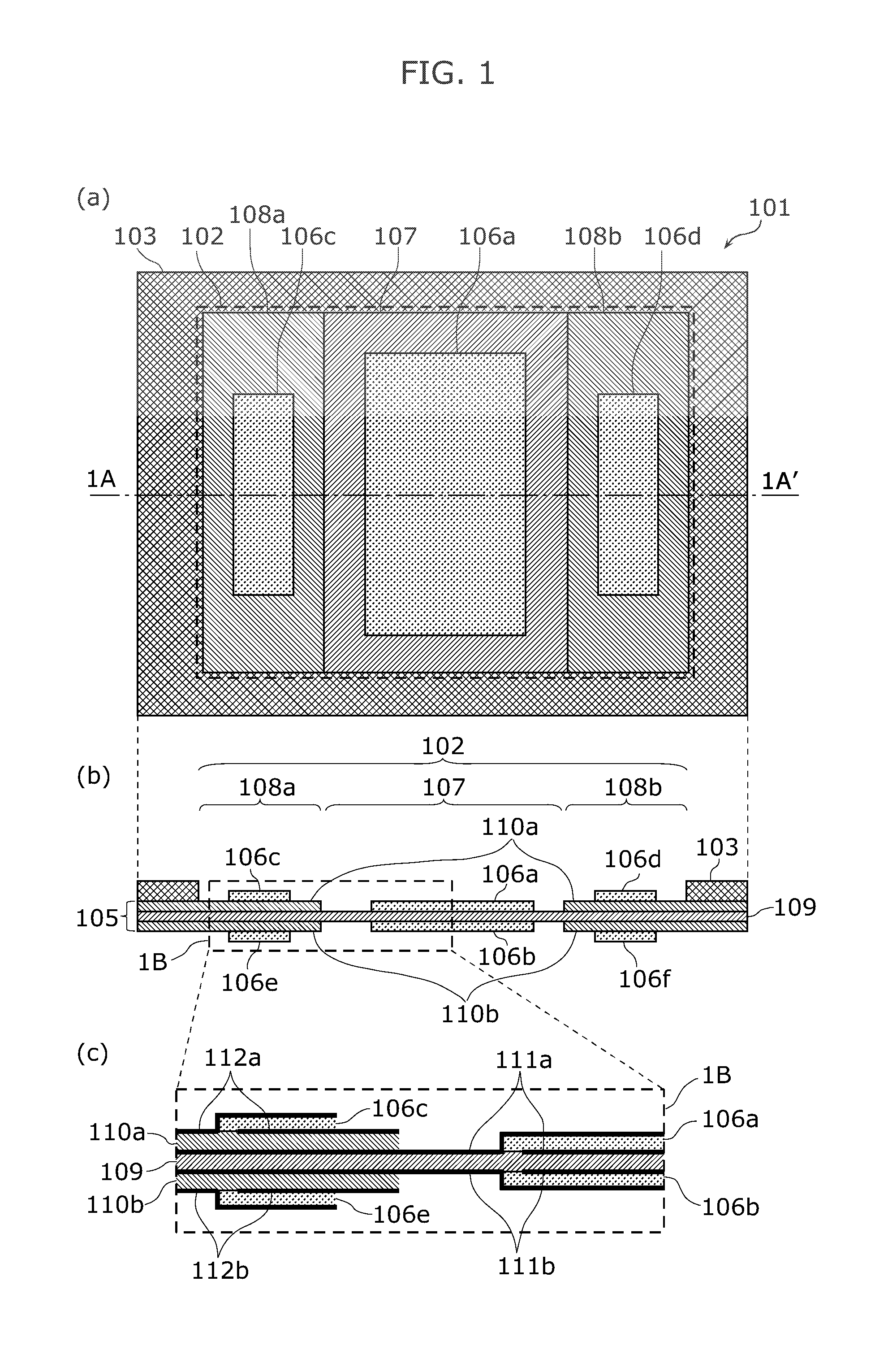
[0083]FIG. 1 is a diagram showing a piezoelectric speaker according to Embodiment 1. In FIG. 1, a piezoelectric speaker 101 to radiate acoustic waves is illustrated. FIG. 1 illustrates, in (a), an upper surface of the piezoelectric speaker 101, and shows a front surface of a side of which acoustic waves are radiated from the piezoelectric speaker 101. FIG. 1 illustrates, in (b), a cross-sectional surface taken along line 1A-1A′ shown in (a) of FIG. 1. FIG. 1 illustrates, in (c), an enlarged image of a portion 1B shown in (b) of FIG. 1 and a cross-sectional surface of an electrode structure.

[0084]As shown in FIG. 1, the piezoelectric speaker 101 includes a piezoelectric diaphragm 102 and a frame 103. Moreover, the piezoelectric speaker 101 includes four external connection terminals 104a to 104d (not illustrated in FIG. 1).

[0085]The piezoelectric diaphragm 102 has a rectangular-like shape and includes a substrate 105 and piezoelectric elements 106a to 106f. Moreover, the piezoelectri...

embodiment 2

[0129]Embodiment 2 shows an example where the piezoelectric speaker 101 according to Embodiment 1 is applied to a piezoelectric speaker array.

[0130]FIG. 4 is a diagram showing a piezoelectric speaker array according to Embodiment 2. FIG. 4 illustrates, in (a), a top surface of a piezoelectric speaker array 201. FIG. 4 illustrates, in (b), a cross-sectional surface of the piezoelectric speaker array 201. The piezoelectric speaker array 201 includes piezoelectric speakers 202a to 202c that are arranged in a linear fashion. Each of the piezoelectric speakers 202a to 202c has the same structure as the piezoelectric speaker 101 according to Embodiment 1.

[0131]The piezoelectric speakers 202a to 202c are arranged such that an interval is equal between the centers of treble-range sound reproduction regions 204a to 204f when the piezoelectric speaker array 201 is viewed in a radiation direction of acoustic waves. Control signals different from each other are provided to the treble-range soun...

embodiment 3

[0141]In Embodiment 3, an edge (edge region) having a flexible material is provided on a long side portion inside the frame 103 according to Embodiment 1 and a peripheral portion of the bass-range sound reproduction region 107 according to Embodiment 1. The other components are similar to the components in Embodiment 1.

[0142]FIG. 7 illustrates a piezoelectric speaker according to

[0143]Embodiment 3. FIG. 7 illustrates, in (a), a top surface of a piezoelectric speaker 301. FIG. 7 illustrates, in (b), a cross-sectional surface taken along line 3A-3A′. FIG. 7 illustrates, in (c), an enlarged image of a portion 3B shown in (b) of FIG. 7.

[0144]In the substrate 105, punching is performed for a long side inside the frame 103 and a peripheral portion of the bass-range sound reproduction region 107. Then, edges 306a to 306d are formed by filling the punched portions with the flexible material.

[0145]Most of the peripheral portion (four sides) of the bass-range sound reproduction region 107 is ...


PUM


Abstract

A piezoelectric speaker is a piezoelectric speaker which radiates acoustic waves by vibrating according to an applied voltage, including (i) a substrate which includes a first region having first bending stiffness against bending of a plane perpendicular to a vibration direction and a second region having second bending stiffness against bending of the perpendicular plane, the second bending stiffness being different from the first bending stiffness, (ii) a first piezoelectric element which is mounted on the first region and to which a voltage of a first frequency band is applied, and (iii) a second piezoelectric element which is mounted on the second region and to which a voltage of a second frequency band different from the first frequency band is applied.

Description

CROSS REFERENCE TO RELATED APPLICATION[0001]The present application is based on and claims priority of Japanese Patent Application No. 2010-269680 filed on Dec. 2, 2010. The entire disclosure of the above-identified application, including the specification, drawings and claims is incorporated herein by reference in its entirety.BACKGROUND OF THE INVENTION[0002](1) Field of the Invention[0003]The present invention relates to piezoelectric speakers which radiate acoustic waves by vibrating according to an applied voltage.[0004](2) Description of the Related Art[0005]Conventionally, speaker arrays, in which many small speakers are arranged, are available. Such speaker arrays control directivity of acoustic waves and realize sound sources that make it possible for users to simultaneously listen to the most appropriate sound (acoustics) at plural listening positions. An electrodynamic method has been mainly used as a method to drive a speaker included in a speaker array.[0006]Recently, i...

Claims


Application Information

Patent Timeline
IPC IPC(8): H04R1/02H04R17/00
CPCH04R1/24H04R17/00H04R2499/15H04R2499/11H04R2430/03
Inventor FUJISE, AKIKOMATSUMURA, TOSHIYUKI
Owner PANASONIC INTELLECTUAL PROPERTY MANAGEMENT CO LTD
Why Eureka
Try Eureka