Dynamic interbody cage anchor system

a cage anchor and dynamic technology, applied in the field of spinal disorders, can solve the problems of nerve root compression and pain, lack of cohesive strength, and spinal nerve roots, and achieve the effect of promoting bone growth and fusion

Active Publication Date: 2012-06-07
AFLATOON KAMRAN
View PDF5 Cites 53 Cited by
  • Summary
  • Abstract
  • Description
  • Claims
  • Application Information

AI Technical Summary

Benefits of technology

[0015]Accordingly, there is provided a system and method of securing an intervertebral fusion cage within the intervertebral space between adjacent vertebra in which one or more slots are provided in an anterior surface of the cage each extending from an oversized aperture. A retention plate having a post and enlarged head is advanced into each slot via the oversized aperture and captured therein. The post is advanced to the terminal end of the plate and secured to vertebral body at its distal end by a bone screw. A locking clip may be slideably positioned on the retention plate to prevent withdrawal of the bone screw. The slots preferably extend to the margins of the anterior surface of the cage in, for example, the pattern of an “X” or an “H”. Sliding of the posts in the slots prevents the system from carrying the vertebral load (load shielding) and permits reduction in the intervertebral space to promote bone growth and fusion by graft material retained in the spacer.

Problems solved by technology

Degeneration of the intervertebral discs and the concomitant instability and translocation of the vertebra is a common cause of back pain and may result from a variety of problems including congenital deformity, age related degeneration, osteoporosis, tumor and disc herniation as a result of trauma.
Disc degeneration, for whatever reason, results in compression of the spinal nerve roots resulting in pain.
However, both posterior and postero-lateral fusion tends to cause bony overgrowth leading to nerve root compression and pain by spinal stenosis.
This, coupled with other risks, limitations and disappointing fusion success rates have caused surgeons searching for alternate fusion means to develop interbody fusion techniques.
When fusion graft material is first placed in the intervertebral space it is soft and lacking in cohesive strength so as to be incapable of remaining in position or carrying any load without assistance.
End caps are employed to prevent subsidence into the cancellous bone although this design suffers, as a result, from a requirement that its central void be pack with graft material prior to insertion.
These rigid appliances span the intervertebral space to maintain the intervertebral disc height and prevent excessive compression of the two vertebrae, which can lead to a weak fusion or even collapse of the graft.
However, they can also lead to stress shielding, in which fusion of the vertebrae to the grafted bone is impeded or prevented entirely because the apparatus prevents adequate contact between the vertebra and the graft.
Resorption of the bone graft can exacerbate this problem.

Method used


Image

  • Dynamic interbody cage anchor system
  • Dynamic interbody cage anchor system
  • Dynamic interbody cage anchor system

Examples


Embodiment Construction

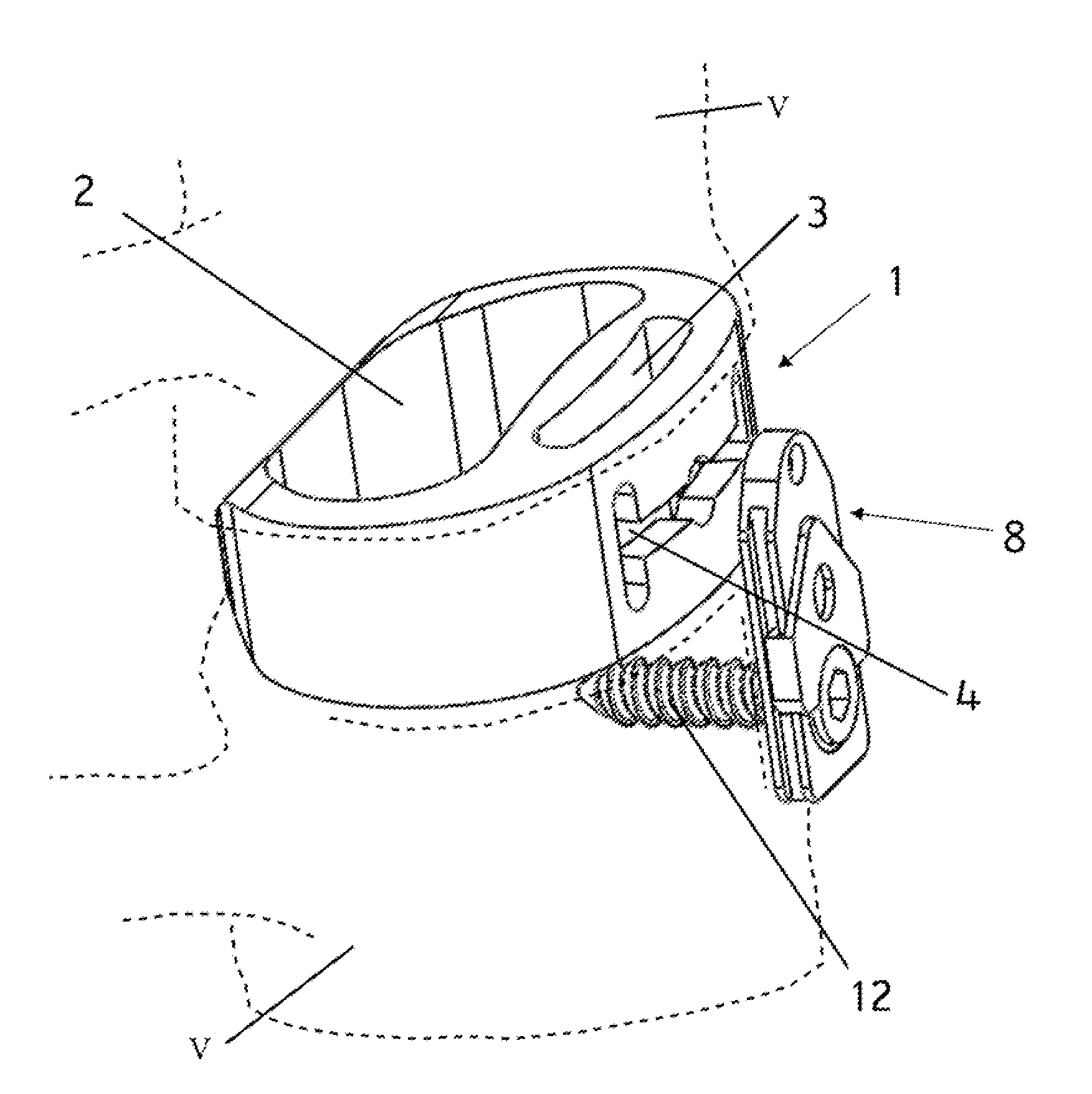
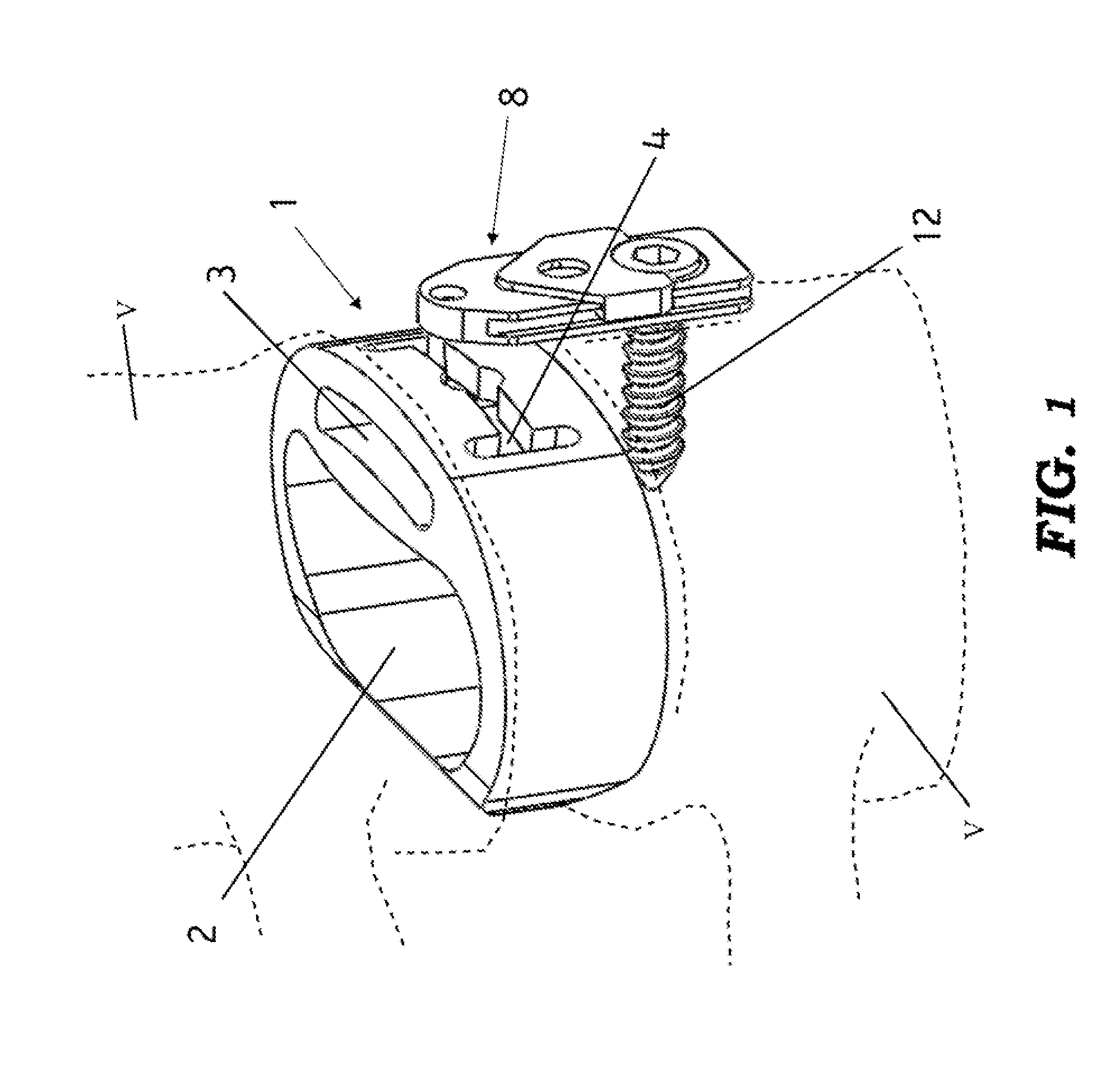
[0030]With reference to FIG. 1, an interbody fusion cage 1 having a generally annular box form surrounding a central void 2 is provided. The void 2 extends from the upper surface of the cage to the lower surface and is provided to be packed with natural or synthetic bone graft material in order to promote bone growth and fusion of the superior and inferior vertebra V between which it will be implanted. The fusion cage 1 is preferably constructed of PEEK (Polyether ether ketone) but may be constructed of any suitable, bio-compatible material such as titanium or Polyoxymethylene. It should be noted that while the box form intervertebral cage has been used as a representative interbody spacer, a variety of interbody spacer types including horizontal and vertical cylindrical cages may also utilize the present invention.

[0031]The representative box form cage 1 is provided with a vertical surface that will be oriented to the anterior face of the spine when implanted between the adjacent v...


PUM


Abstract

A system and method of securing an intervertebral fusion cage within the intervertebral space between adjacent vertebra in which one or more slots are provided in an anterior surface of the cage each extending from an oversized aperture. A retention plate having a post and enlarged head is advanced into each slot via the oversized aperture and captured therein. The post is advanced to the terminal end of the plate and secured to vertebral body at its distal end by a bone screw. A locking clip is slideably positioned on the retention plate to prevent withdrawal of the bone screw. The slots preferably extend to margins of the anterior surface of the cage in, for example, the pattern of an “X” or an “H”. Sliding of the posts in the slots prevents the system from carrying the vertebral load (load shielding) and permits reduction in the intervertebral space to promote bone growth and fusion by graft material retained in the spacer.

Description

CROSS-REFERENCE TO RELATED APPLICATION(S)[0001]The present application derives priority from provisional application 61 / 352,539, filed on Jun. 8, 2010 which is incorporated herein by reference.BACKGROUND OF THE INVENTION[0002]1. Field of the invention[0003]The present invention relates generally to devices and methods for treating spinal disorders and more specifically to a system and method for securing in place an intervertebral device for aligning and maintaining the relative position of adjacent vertebrae to facilitate immobilization of the vertebra through fusion while avoiding stress shielding.[0004]2. Description of the Background[0005]Degeneration of the intervertebral discs and the concomitant instability and translocation of the vertebra is a common cause of back pain and may result from a variety of problems including congenital deformity, age related degeneration, osteoporosis, tumor and disc herniation as a result of trauma. Disc degeneration, for whatever reason, resul...

Claims


Application Information

Patent Timeline
Patent Type & Authority Applications(United States)
IPC IPC(8): A61F2/44
CPCA61F2/4465A61F2002/2817A61F2002/2835A61F2002/30166A61F2002/30179A61F2002/30431A61F2310/00029A61F2002/30517A61F2002/30578A61F2002/30794A61F2002/4475A61F2310/00017A61F2310/00023A61F2002/30504A61F2002/305A61F2002/30593A61F2002/3079
Inventor AFLATOON, KAMRANMAURER, CHRIS
Owner AFLATOON KAMRAN
Why Eureka
Try Eureka