Method of generating superheated steam in a solar thermal power plant and solar thermal power plant

a solar thermal power plant and superheated steam technology, applied in the direction of steam generation using solar heat, machines/engines, lighting and heating apparatus, etc., can solve the problems of reducing the endurance strength of the affected components, thermal stresses in the corresponding materials of the guide tube,

Inactive Publication Date: 2012-06-14
DEUTSCHES ZENTRUM FUER LUFT & RAUMFAHRT EV
View PDF6 Cites 18 Cited by
  • Summary
  • Abstract
  • Description
  • Claims
  • Application Information

AI Technical Summary

Benefits of technology

[0005]In accordance with the present invention, a method is provided by me...

Problems solved by technology

Such temperature gradients cause thermal stresses in the corresponding materials of a gui...

Method used


Image

  • Method of generating superheated steam in a solar thermal power plant and solar thermal power plant
  • Method of generating superheated steam in a solar thermal power plant and solar thermal power plant
  • Method of generating superheated steam in a solar thermal power plant and solar thermal power plant

Examples


first embodiment

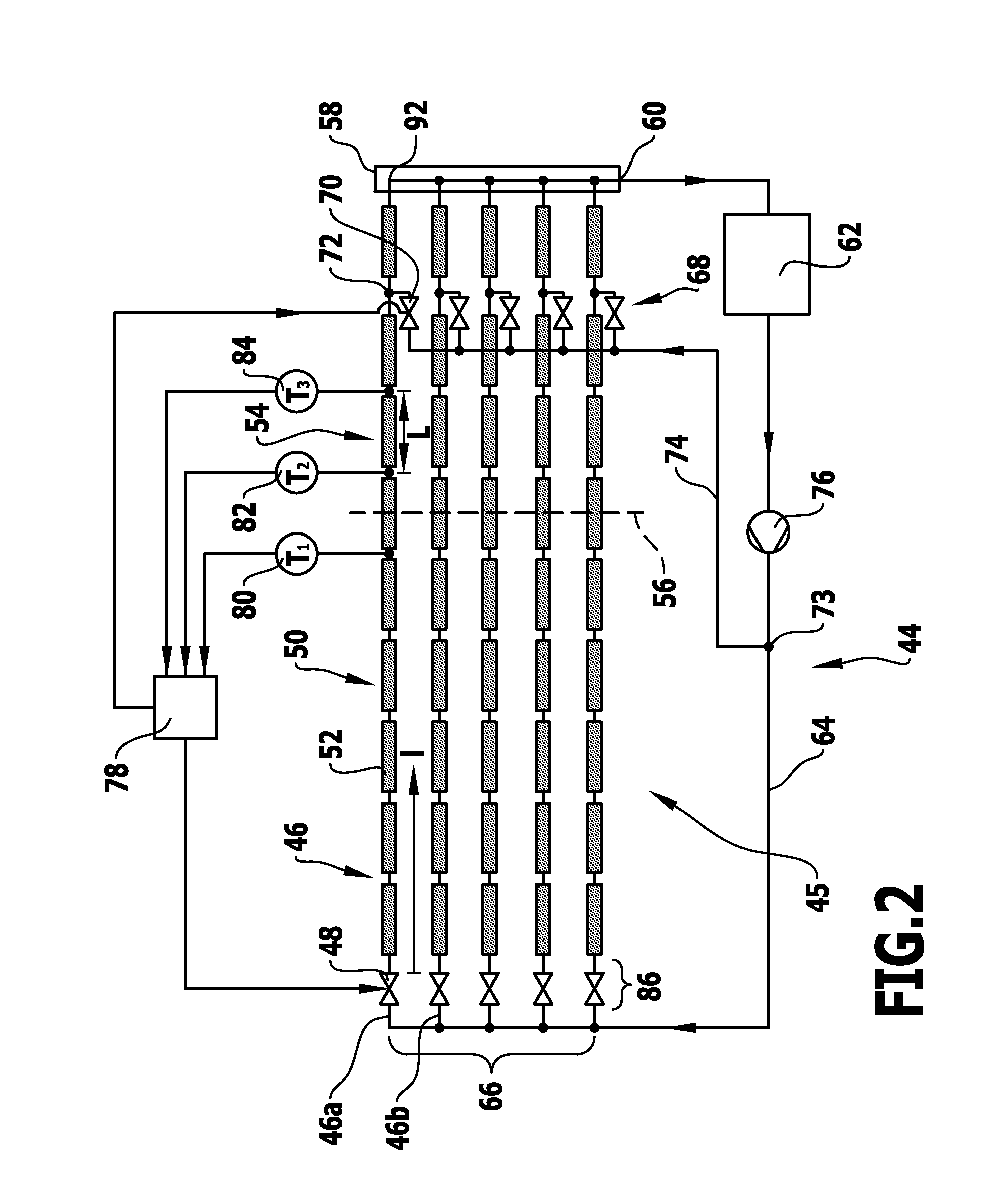
[0052]a solar thermal power plant according to the invention, which is shown in FIG. 2 and denoted by 44, comprises a steam generating stage 45 having a plurality of flow sections 46 (46a, 46b, etc.) arranged in parallel. These are followed by an evaporator zone 50 having a solar collector device 52. The solar collector device 52 comprises for example a plurality of trough collectors.

[0053]The evaporator zone 50 is followed in the flow section 46 by a superheater zone 54. This is likewise disposed at the solar collector device 52. Situated between the evaporator zone 50 and the superheater zone 54 is the evaporation end point 56. This may be situated inside a trough collector. As is explained in greater detail below, the aim of the control method according to the invention is to fix the evaporation end point 56 spatially, i.e. along the flow section 10, and hence fix in position the evaporation end point 56.

[0054]Adjoining the superheater zones 54 of the flow sections 46 is a collec...

second embodiment

[0075]a solar thermal power plant according to the invention that is shown schematically in FIG. 3 and denoted there by 94 is in principle identical in construction to the solar thermal power plant 44. For identical elements identical reference characters are used. An additional injection device 96 is provided, by means of which liquid heat transfer medium is injectable into the evaporator zone 50. In this case, at the respective flow sections 46 an injection point 98 is disposed in the evaporator zone 50 downstream of the first temperature sensor 80, i.e. the respective injection point 98 lies between the first temperature sensor 80 and the evaporation end point 56.

[0076]The injection device comprises for example a control valve 100 associated with each flow section 46. The control valves 100 are connected fluidically to the return line 64. For example from a junction 102 a line 104 leads to the control valves 100 of the flow sections 46. The junction 102 in turn is disposed for ex...


PUM


Abstract

A method of generating superheated steam in a solar thermal power plant is provided, in which in a flow section for heat transfer medium steam is generated by solar energy in an evaporator zone and the steam is superheated by solar energy in a superheater zone. An evaporation end point of the evaporator zone is fixed in position in a control method, in which a spatial temperature gradient in the superheater zone and a temperature in the evaporator zone are determined and the mass flow of heat transfer medium in the flow section is adjusted in dependence upon the temperature gradient and the measured temperature in the evaporator zone.

Description

CROSS-REFERENCE TO RELATED APPLICATIONS[0001]This application is a continuation of international application number PCT / EP2010 / 057982 filed on Jun. 8, 2010 and claims the benefit of German application number 10 2009 025 455.2 filed on Jun. 15, 2009, which are both incorporated herein by reference in their entireties and for all purposes.FIELD OF THE INVENTION[0002]The invention relates to solar thermal power plant and methods of generating superheated steam in a solar thermal power plant. Within the solar thermal power plant, in a flow section for heat transfer medium, steam is generated by solar energy in an evaporator zone and the steam is superheated by solar energy in a superheater zone.BACKGROUND OF THE INVENTION[0003]Solar thermal power plants may have a steam generating stage, wherein the steam generating stage comprises at least one collector branch having a flow section for heat transfer medium comprising an evaporator zone and a superheater zone. At the transition from the...

Claims


Application Information

Patent Timeline
IPC IPC(8): F03G6/00F01K13/00
CPCF22B1/006Y02E10/46F22B29/08
Inventor FELDHOFF, JAN FABIANECK, MARKUS
Owner DEUTSCHES ZENTRUM FUER LUFT & RAUMFAHRT EV
Why Eureka
Try Eureka