
Tire and tire manufacturing method

a manufacturing method and tire technology, applied in the direction of transportation and packaging, other domestic articles, and multiple inflatable chambers, can solve the problem of limit to post-use rubber recycling applications, and achieve the effect of increasing joint strength, increasing tire performance characteristics such as uniformity, and reducing the number of parts

Inactive Publication Date: 2012-06-14
BRIDGESTONE CORP
View PDF19 Cites 7 Cited by
  • Summary
  • Abstract
  • Description
  • Claims
  • Application Information

AI Technical Summary

Benefits of technology

[0068]Due to being configured as described above, a tire of the first aspect of the present invention exhibits the excellent advantageous effect of being able to ensure ample strength of the joint portion of tire structuring members made of a thermoplastic material.
[0069]Due to a tire of the second aspect of the present invention being configured as described above, the joint strength can be increased, and tire performance characteristics such as uniformity can be raised.
[0070]Due to a tire of the third aspect of the present invention being configured as described above, the joint strength of can be raised yet further.
[0071]Due to a tire of the fourth aspect of the present invention being configured as described above, the tire can be held firmly retained on a rim.
[0072]Due to a tire of the fifth aspect of the present invention being configured as described above, the amount of the first thermoplastic material as a proportion of the tire as a whole increases, and recyclability is raised.
[0073]Due to a tire of the sixth aspect of the present invention being configured as described above, the joint strength can be increased yet further.

Problems solved by technology

However there is a limit to post-use rubber recycling applications, and disposal is performed by such methods as combustion to give thermal recycling and by shredding for use as a road pavement material.

Method used


Image

  • Tire and tire manufacturing method
  • Tire and tire manufacturing method
  • Tire and tire manufacturing method

Examples


Embodiment Construction

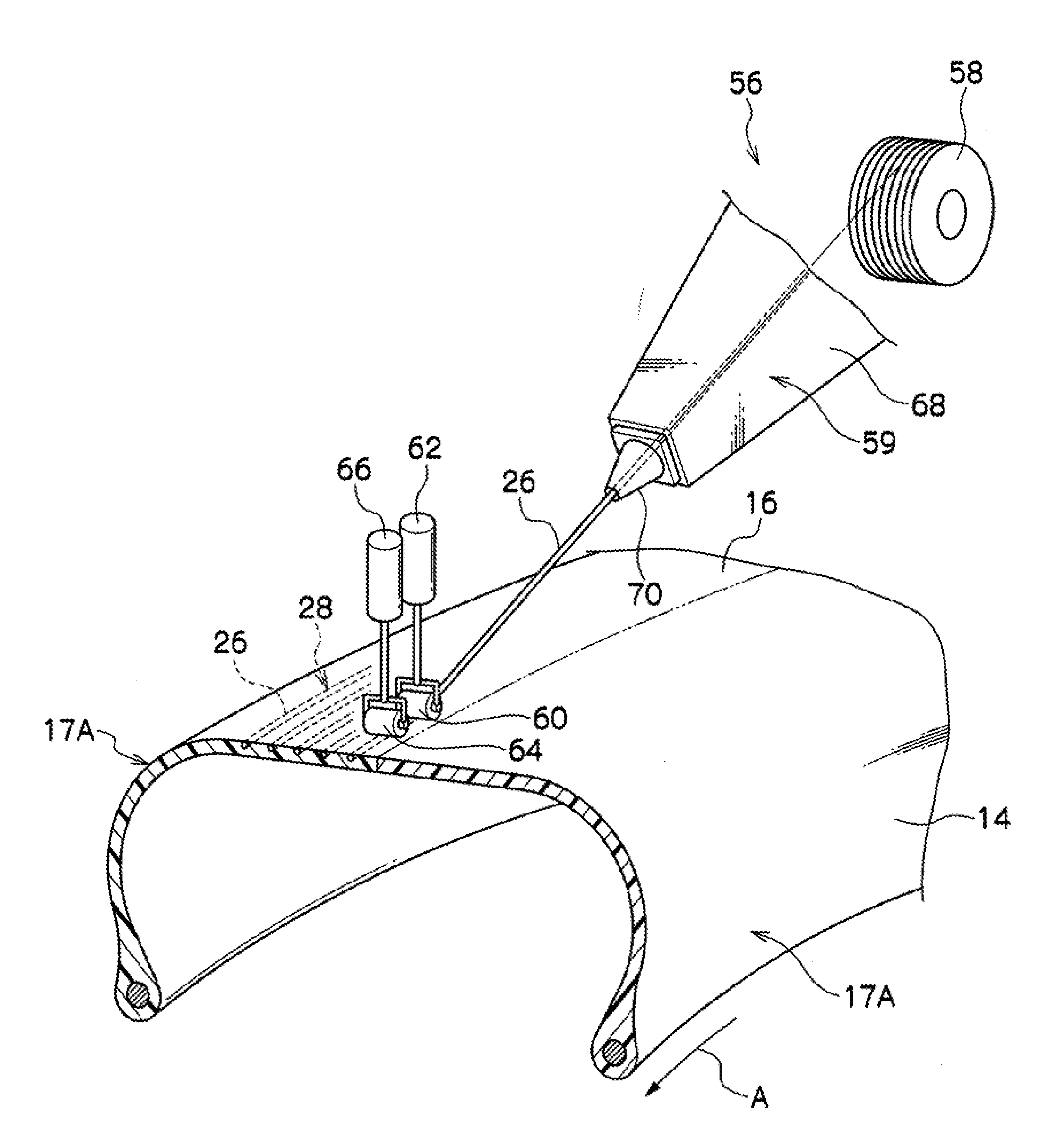
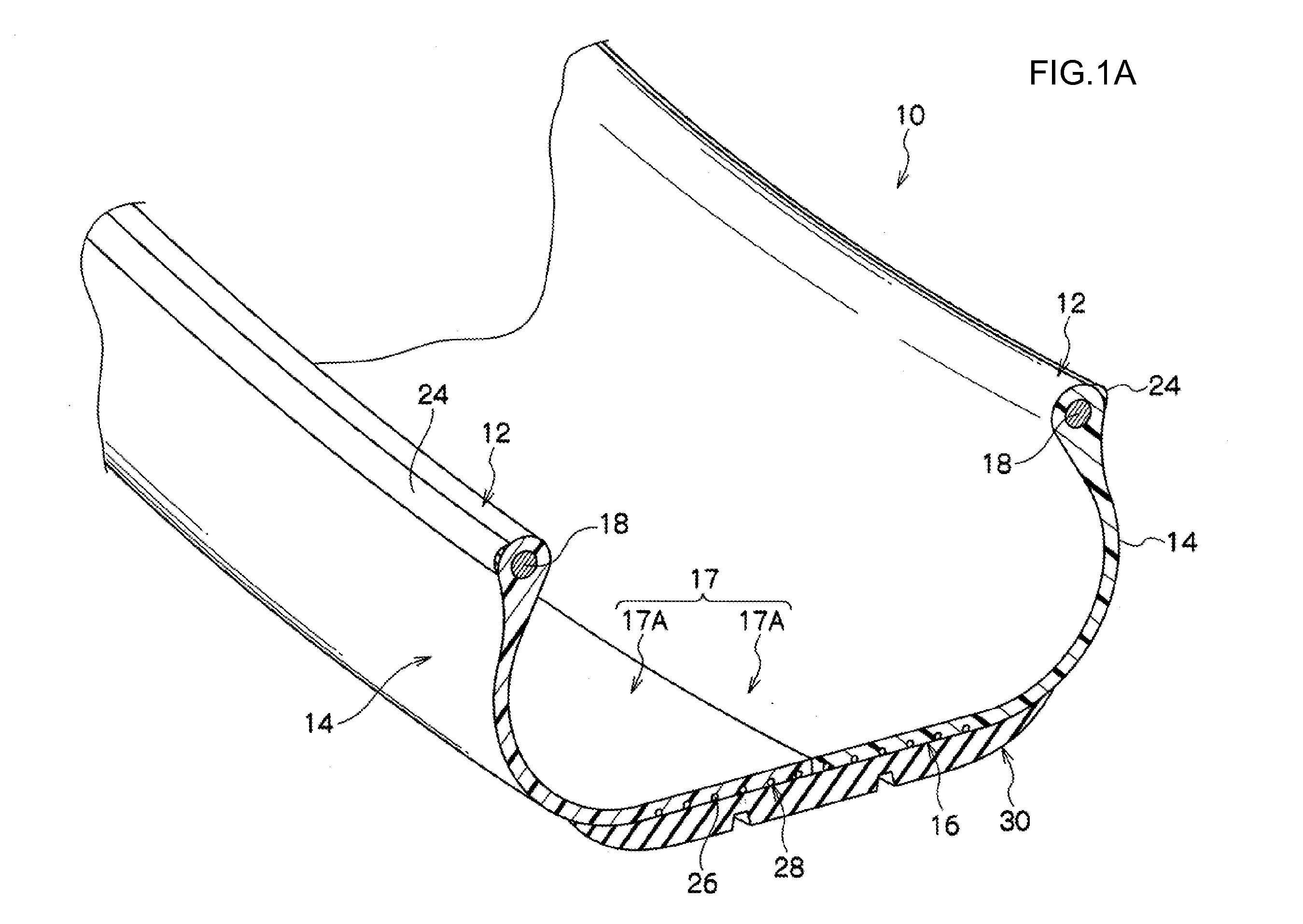
[0107]Explanation follows regarding a tire of an exemplary embodiment of a tire of the present invention, with reference to the drawings. As shown in FIG. 1, a tire 10 of the present exemplary embodiment exhibits a cross-sectional profile substantially the same as that of a conventional ordinary rubber pneumatic tire.

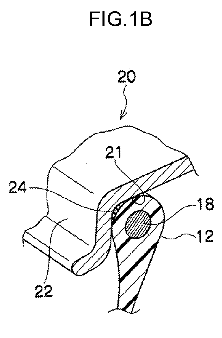
[0108]The tire 10 is equipped with a tire case (serving as an example of a tire frame member) 17 configured by: a pair of bead sections 12 that make contact with a bead seat 21 and a rim flange 22 of a rim 20; side sections 14 that extend from the bead sections 12 towards the tire radial direction outside; and a crown section 16 that connects together the tire radial direction outside edge of one of the side sections 14 and the tire radial direction outside edge of the other of the side sections 14.

[0109]The tire case 17 of the present exemplary embodiment is formed from a first thermoplastic material.

[0110]The tire case 17 of the present exemplary embodiment is formed ...


PUM

PropertyMeasurementUnit
Vicat softening temperatureaaaaaaaaaa
tensile break point elongationaaaaaaaaaa

Abstract

Sufficient strength of a joint portion is secured in a tire configured by joining together plural tire structuring members formed from a thermoplastic material.A welding thermoplastic material 43 that has been melted is extruded towards joining locations on two tire halves 17A formed from a first thermoplastic material that have been aligned so as to face each other and abut, such that the one tire half 17A and the other tire half 17A are welded together with the welding thermoplastic material 43. Degradation of the thermoplastic material forming the tire halves 17A is suppressed since the tire halves 17A are not themselves melted, and sufficient strength of the joint portion is secured.

Description

TECHNICAL FIELD[0001]The present invention relates to a tire for rim mounting and a tire manufacturing method, and in particular to a tire with at least a portion formed from a thermoplastic material and a tire manufacturing method of the same.BACKGROUND ART[0002]Pneumatic tires configured with rubber, organic fiber material, and steel members are traditionally employed on vehicles such as cars.[0003]However there is a limit to post-use rubber recycling applications, and disposal is performed by such methods as combustion to give thermal recycling and by shredding for use as a road pavement material.[0004]There is demand recently to use materials such as thermoplastic resins and thermoplastic elastomers as tire materials due to their advantages from the perspectives of weight reduction and ease of recycling.[0005]For example, a pneumatic tire formed using a thermoplastic polymer material is described in Patent Document 1.[0006]Patent Document 1: Japanese Patent Application Laid-Open...

Claims


Application Information

Patent Timeline
Patent Type & Authority Applications(United States)
IPC IPC(8): B60C15/00B60C1/00B29D30/00
CPCB29C65/103Y10T152/10819B29C65/5042B29C66/1122B29C66/1142B29C66/1162B29C66/1282B29C66/12841B29C66/5227B29C66/54B29C66/547B29C66/63B29C66/636B29C66/73921B29C66/8242B29C66/83413B29C66/83415B29C66/83417B29C66/8362B29D30/0061B29D30/08B29D30/1621B29D2030/0072B29D2030/086B29L2030/00B60C5/01B60C5/22B29C65/5092B29C66/543B29C66/545B29C65/4815Y10T152/10B29C65/40B29C66/81465B29C66/7212B29C66/72141B29C66/71B29C66/65B29K2305/00B29K2021/00B29K2021/003
Inventor KOUNO, YOSHIHIDEKON, SEIJI
Owner BRIDGESTONE CORP
Learn More