Thermal Impedance Matching Using Common Materials

a technology of impedance matching and common materials, applied in the field of heat management systems, can solve the problems of increasing system size, weight/material/cost, high process inefficiency, etc., and achieve the effect of minimizing temperature change and dissipating hea

Inactive Publication Date: 2012-06-14
ROBERTSON TRANSFORMER
View PDF2 Cites 15 Cited by
  • Summary
  • Abstract
  • Description
  • Claims
  • Application Information

AI Technical Summary

Benefits of technology

[0016]Another aspect of the invention is directed to a method of dissipating heat from a source of heat. The method comprises the steps of: (1) providing a source of heat; (2) providing a first layer of a first material having a first thermal conductivity adjacent the source of heat; (3) providing a second layer of ...

Problems solved by technology

When natural convection is not adequate, a power device typically a blower 6, is used to provide a higher level of mass flow and to gain the desired thermal equilibrium, thus consuming additional energy, increasing the size of the system and adds weight/material/cost.
A disparity of thermal impedances makes this process highly ineffective but nearly universally accepted as an adequate and reasonable approach in the art.
Radiation typically does not come into play in most applications involving living spaces, as these applications require higher temperatures than can ...

Method used


Image

  • Thermal Impedance Matching Using Common Materials
  • Thermal Impedance Matching Using Common Materials
  • Thermal Impedance Matching Using Common Materials

Examples


example

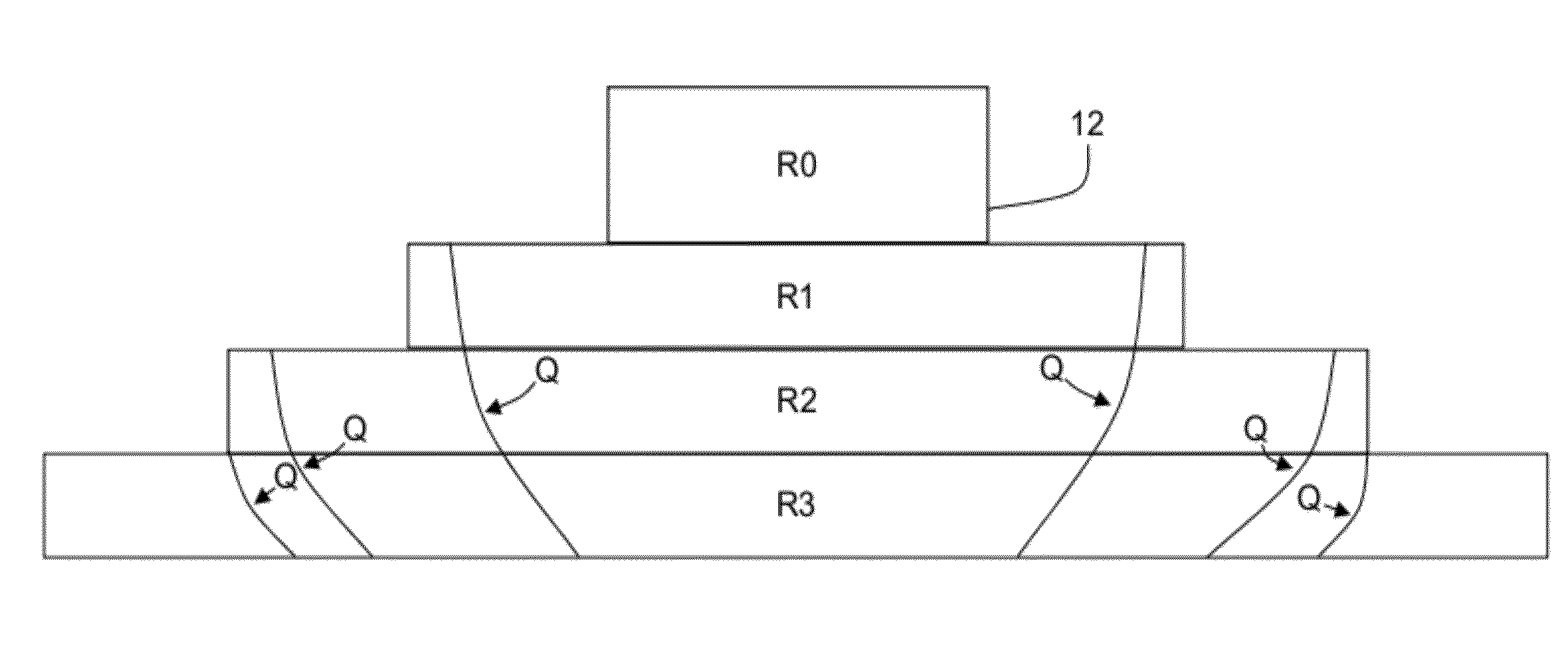
[0135]FIGS. 31-36 show an embodiment of the present invention incorporating a variable-gradient layer. In this embodiment, a system 700 has a 30 Watt LED 702 where s first layer 704 of a copper, a second layer 710 of aluminum, a third layer 712 of a stainless steel, and a fourth layer 714 of variable-gradient material.

[0136]The fourth layer 714 has a distributed thermal impedance, such that a thermal impedance gradient is established within the fourth layer 714. In this embodiment, the fourth layer 714 has a low thermal impedance at an interface between the third layer 712 and the fourth layer 714 relative to the thermal impedance of the third layer 712 to a much lower thermal impedance relative to the third layer 712 at an interface between the fourth layer 414 an ambient layer, typically air or insulation.

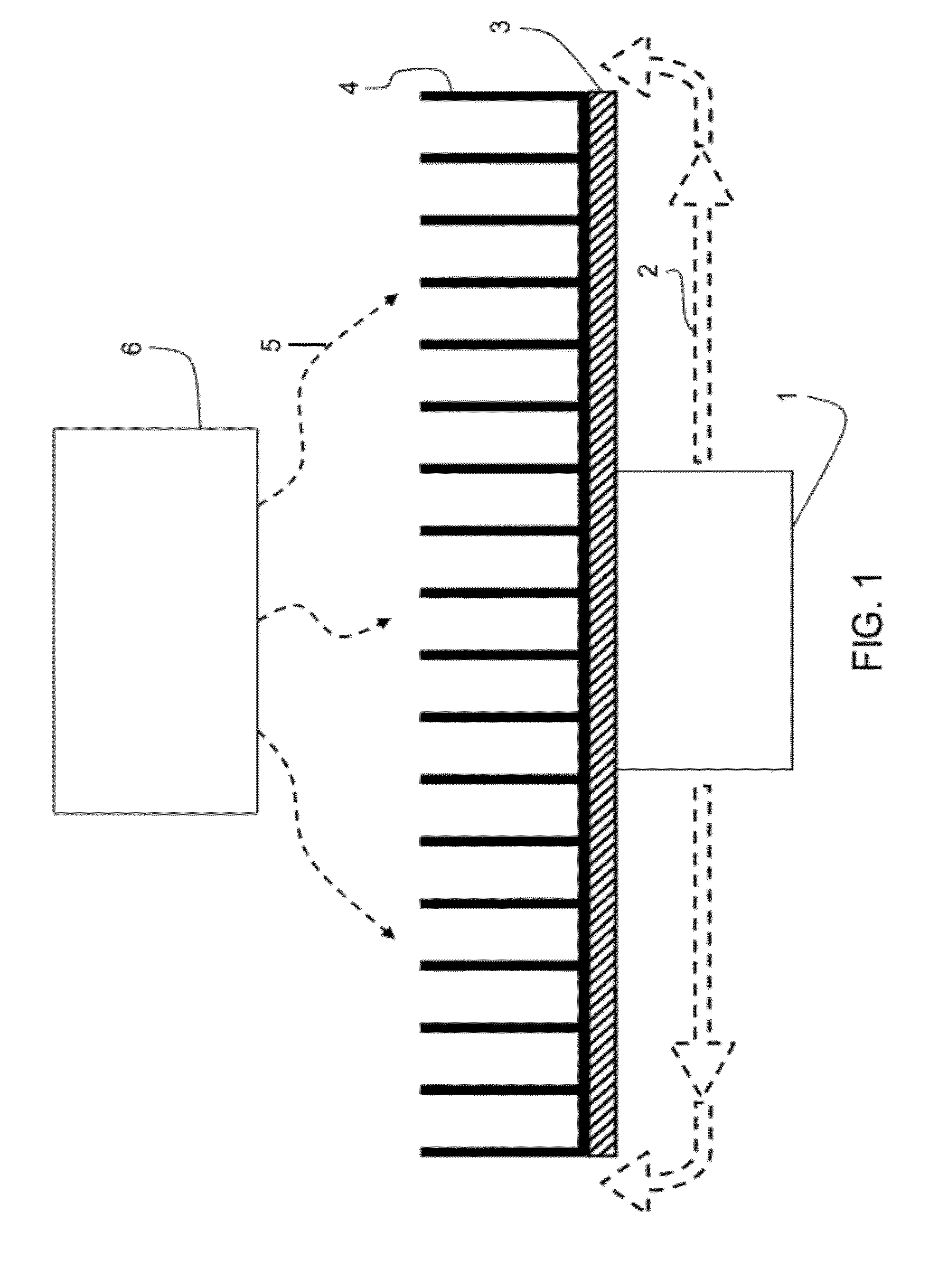
[0137]In this embodiment, the fourth layer 714 was formed by suspending stainless steel wool 720 from the third layer 712. The steel wool 720 was then impregnated with a lower th...


PUM


Abstract

A device and method for dissipating heat from a source of heat is described. A plurality of layers of thermally conductive materials receives a flow of heat from a source of heat. A first layer of the plurality of layers receives the flow of heat from the source of heat and redirects and transfers the flow of heat to a second of the plurality of layers. Each layer has a separate preselected thermal impedance to control a desired temperature change across the plurality of layers and to maintain a desired operating temperature of the source heat.

Description

CROSS-REFERENCE TO RELATED APPLICATIONS[0001]This Application is a continuation-in-part application of co-pending U.S. application Ser. No. 13 / 375,060 filed on Nov. 29, 2011 which is a national stage filing under 35 U.S.C. §371 of PCT / US2011 / 022534 which has an international filing date of Jan. 26, 2011 and which was published as WO 2011 / 094282 A1 on Aug. 4, 2011 and which claimed the benefit of U.S. Provisional Patent Application No. 61 / 298,406 filed Jan. 26, 2010. The contents of all three applications are incorporated herein by reference as if fully set forth herein.FEDERALLY SPONSORED RESEARCH OR DEVELOPMENT[0002]N / ATECHNICAL FIELD[0003]The invention relates to heat management systems. More particularly, the invention relates to heat management systems wherein a heat flow is vectored to enhance rapid dissipation into regions less thermally conductive than the source element. Although applicable anywhere heat flow is critical, an immediate and important application is in lighting...

Claims


Application Information

Patent Timeline
IPC IPC(8): F28F27/00F28F21/00
CPCC07C209/02C07F7/006F21Y2105/001F21Y2101/02F21V29/004C07F7/003F21V29/70F21V29/85F21Y2105/10F21Y2115/10
Inventor BEASLEY, DENNY D.
Owner ROBERTSON TRANSFORMER
Why Eureka
Try Eureka