Conveyor Assembly

a conveyor and assembly technology, applied in the direction of conveyor parts, loading/unloading, conveyors, etc., can solve the problems of lost material being transferred, restricted the inlet of the swing auger is restricted to positioning along an arced path,

Inactive Publication Date: 2012-06-14
MERIDIAN MFG
View PDF7 Cites 8 Cited by
  • Summary
  • Abstract
  • Description
  • Claims
  • Application Information

AI Technical Summary

Benefits of technology

[0076]ix) Swing auger has telescoping motion by the use of a hydraulic cylinder mounted internally to the lower fixed tube assembly at one end and the lower section of the tube assembly in motion. No other competitor's auger swing offers this fe

Problems solved by technology

The hopper at the inlet of the swing auger however is restricted to positioning along an arced path which is difficult to align with the discharge hopper of a transport container.
Often due to the narrow space between wheel sets within which a discharge hopper on a transport container is located, it is not possible to displace the swing auger is an arcing motion under the transport container parked beside the main auger without multiple steps of advancing and subsequent reversal of the vehicle position for proper alignment with the discharge hopper on th

Method used


Image

  • Conveyor Assembly
  • Conveyor Assembly
  • Conveyor Assembly

Examples


Embodiment Construction

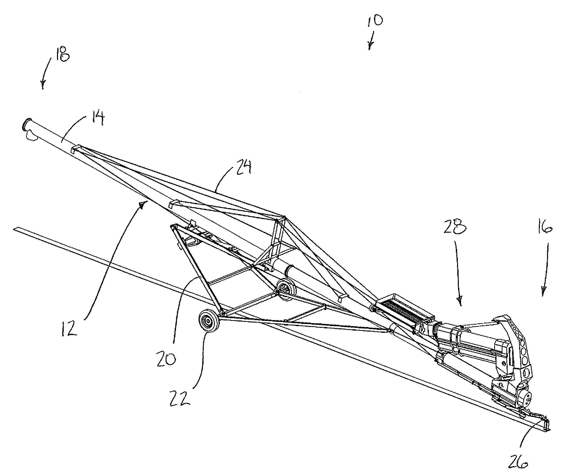
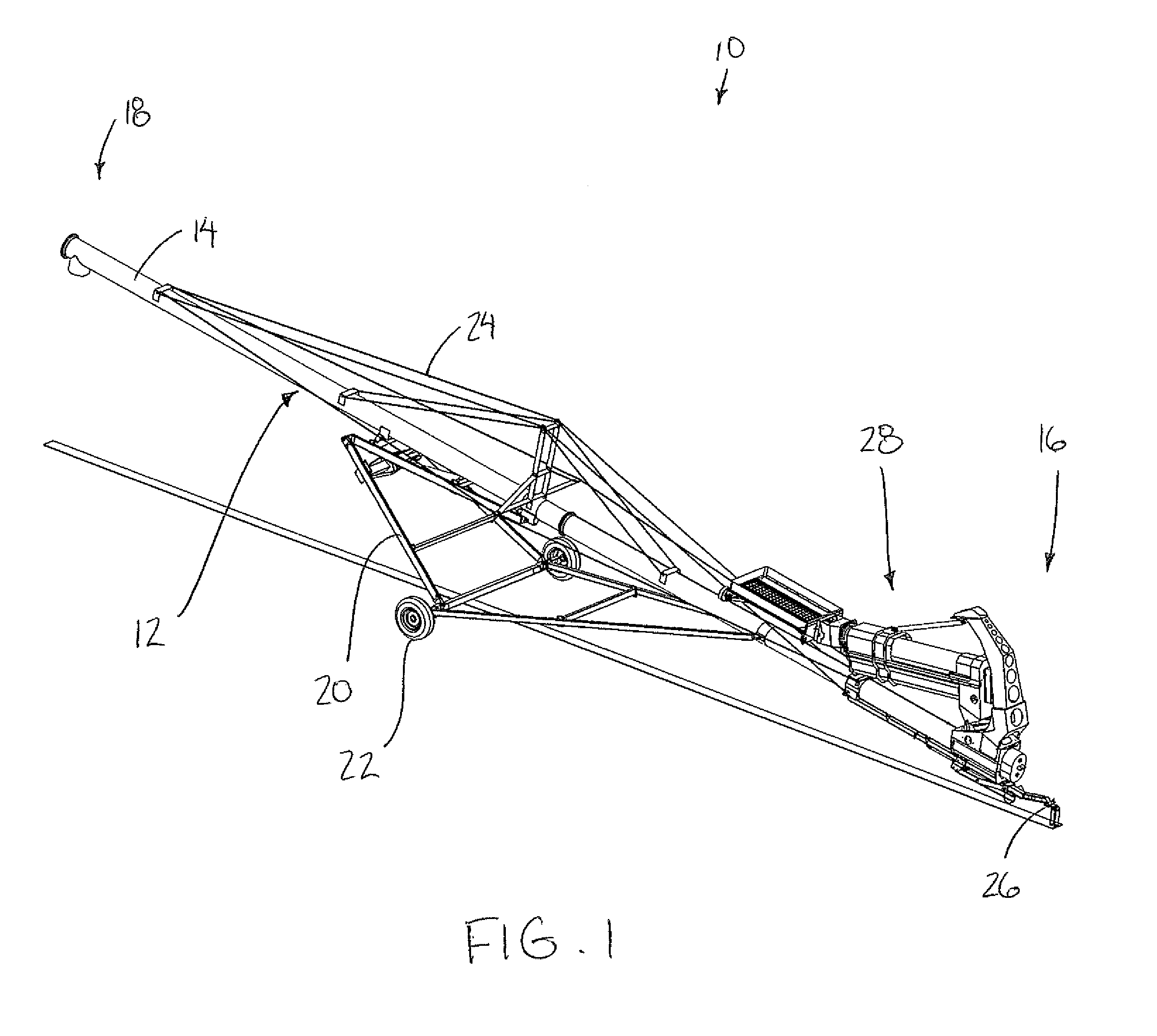
[0088]Referring to the accompanying figures there is illustrated a conveyor assembly generally indicated by reference numeral 10. The assembly 10 is suited for use as an agricultural auger for conveying particulate material, for example grain, seed or other similarly particulate materials.

[0089]The assembly 10 includes a main conveyor 12 comprised of a main conveyor tube 14 which is elongate in a respective longitudinal direction between an inlet end 16 and an outlet end 18. A main conveying member within the main conveyor tube 14 comprises an auger (not shown) in the illustrated embodiment which is rotatable about a longitudinal axis thereof to convey the particulate material from the inlet end to the outlet end.

[0090]The main conveyor also comprises a frame 20 which supports the main conveyor tube 14 on wheels 22 for rolling movement generally in the longitudinal direction of the conveyor. The frame comprises an adjustable linkage which supports the main conveyor through a range o...


PUM


Abstract

A conveyor assembly includes a main conveyor and a swing auger assembly pivotally coupled to an inlet end of the main conveyor for loading particulate material into the main conveyor. The swing auger assembly includes two first and second augers which are slidable relative to one another to vary a length of the swing auger assembly between a loading hopper at an inlet end of the swing auger assembly and the main conveyor connected at an outlet end of the swing auger. The swing auger assembly is suspended from an overhead support member extending upwardly from the inlet end of the main conveyor such that the swing auger assembly is pivotal through an intermediate position overtop of the main conveyor between first and second laterally offset positions on opposing sides of the main conveyor.

Description

FIELD OF THE INVENTION[0001]The present invention relates to a conveyor assembly including a main conveyor and a swing auger assembly for loading the main conveyor in which the swing auger assembly includes two auger sections which are slidable relative to one another to vary a length of the swing auger assembly and in which the swing auger assembly is suspended from an overhead support member for swinging motion overtop of the main conveyor between offset positions on opposing sides of the main conveyor.BACKGROUND[0002]It is common to use grain augers and the like to transfer grain or other particulate material from a source area to a target area, for example from a transport container to a bin or other storage type container. Transport containers generally involve a container supported for rolling movement along the ground by wheels spaced apart at opposing ends of the container. A hopper type discharge is then typically located between the wheels below the container for dischargi...

Claims


Application Information

Patent Timeline
IPC IPC(8): B65G33/14
CPCB65G33/32A01C15/003
Inventor ZAZULA, BRADLEY METROLANDRY, MICHAEL ROSSDIXON, WILLIAM LORNSCHERLE, LESLIE DARENHOUSSIAN, TERRY DOUGLASHOLODRYGA, VICTOR JOHN
Owner MERIDIAN MFG
Why Eureka
Try Eureka