Scanning electron microscope

a scanning electron microscope and electron microscope technology, applied in the field of scanning electron microscope, can solve the problems of destroying the observation object, the observation object unavoidably loses its function, and cannot be used for its intended purpose any more,

Active Publication Date: 2012-06-14
HONDA MOTOR CO LTD
View PDF5 Cites 7 Cited by
  • Summary
  • Abstract
  • Description
  • Claims
  • Application Information

AI Technical Summary

Benefits of technology

[0014]According to the present invention, because the observation object can be attracted to the lens barrel via the seal member and fixed in direct and close contact with the lens barrel when a vacuum is created in the lens barrel by the vacuum pump, it is possible to obtain the advantage that an observation object which is conventionally too large to fit in a sample chamber can be directly observed without any preliminary processing.

Problems solved by technology

However, once an observation object, such as an automobile part, is processed by, for example, cutting, the observation object unavoidably loses its function and cannot be used for its intended purpose any more.
In other words, cutting a sample out of an observation object is destroying the observation object.
For example, when a sample small enough to fit in the sample chamber is cut out of the bonnet of a vehicle as an observation object to observe the paint applied thereto, the bonnet has a hole and cannot be used for its intended purpose any more.
Thus, the conventional scanning electron microscope is not suited for continued observation of changes over time of an observation object (automobile part as described above) which undergoes deterioration or wear as the vehicle is used.
This is a problem stemming from the fact that the conventional scanning electron microscope allows observation of only a sample which is at least small enough to fit in the sample chamber and in which an observed part can be changed by driving the table.
However, the conventional scanning electron microscope has a condenser lens or objective lens made up of a magnetic field coil in the lens barrel, and the condenser lens or objective lens cannot be reduced in size any more because of the structure of the magnetic field coil.
It is, therefore, difficult to reduce the size and weight of the lens barrel itself.
Another reason why reduction in weight of the lens barrel is difficult is that the lens barrel is required to have sufficient strength to support a photomultiplier having relatively large length and weight because the photomultiplier with an elongated shape is directly mounted on a side of the lens barrel.
In addition, the necessity to create a vacuum in the lens barrel and on the sample surface which results from the elimination of the sample chamber and adverse effects during observation due to vibration of the lens barrel which is more likely to occur when the lens barrel is made light and small (for example, the compositional image or topographic image displayed on the display may be blurred and difficult to observe) may arise as new problems.

Method used


Image

  • Scanning electron microscope
  • Scanning electron microscope
  • Scanning electron microscope

Examples


Embodiment Construction

[0021]Description is hereinafter made of an embodiment of the present invention in detail with reference to accompanying drawings.

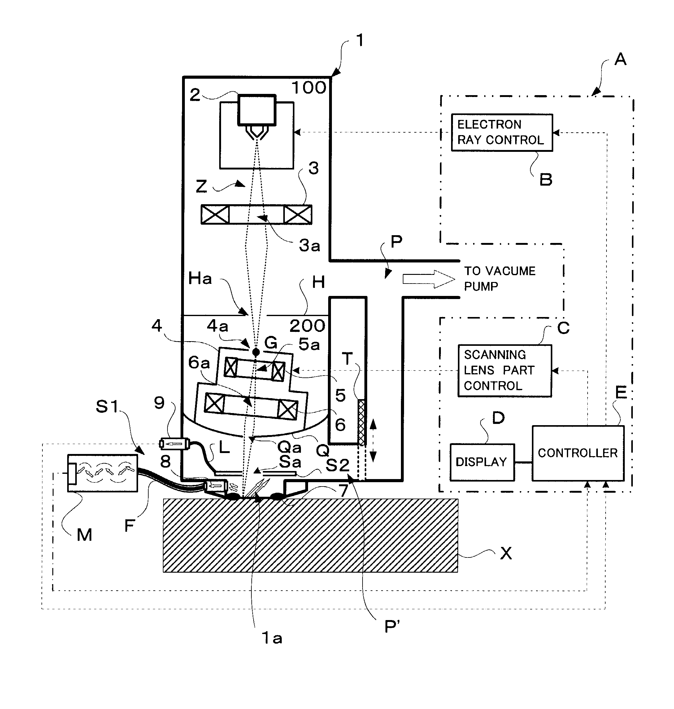
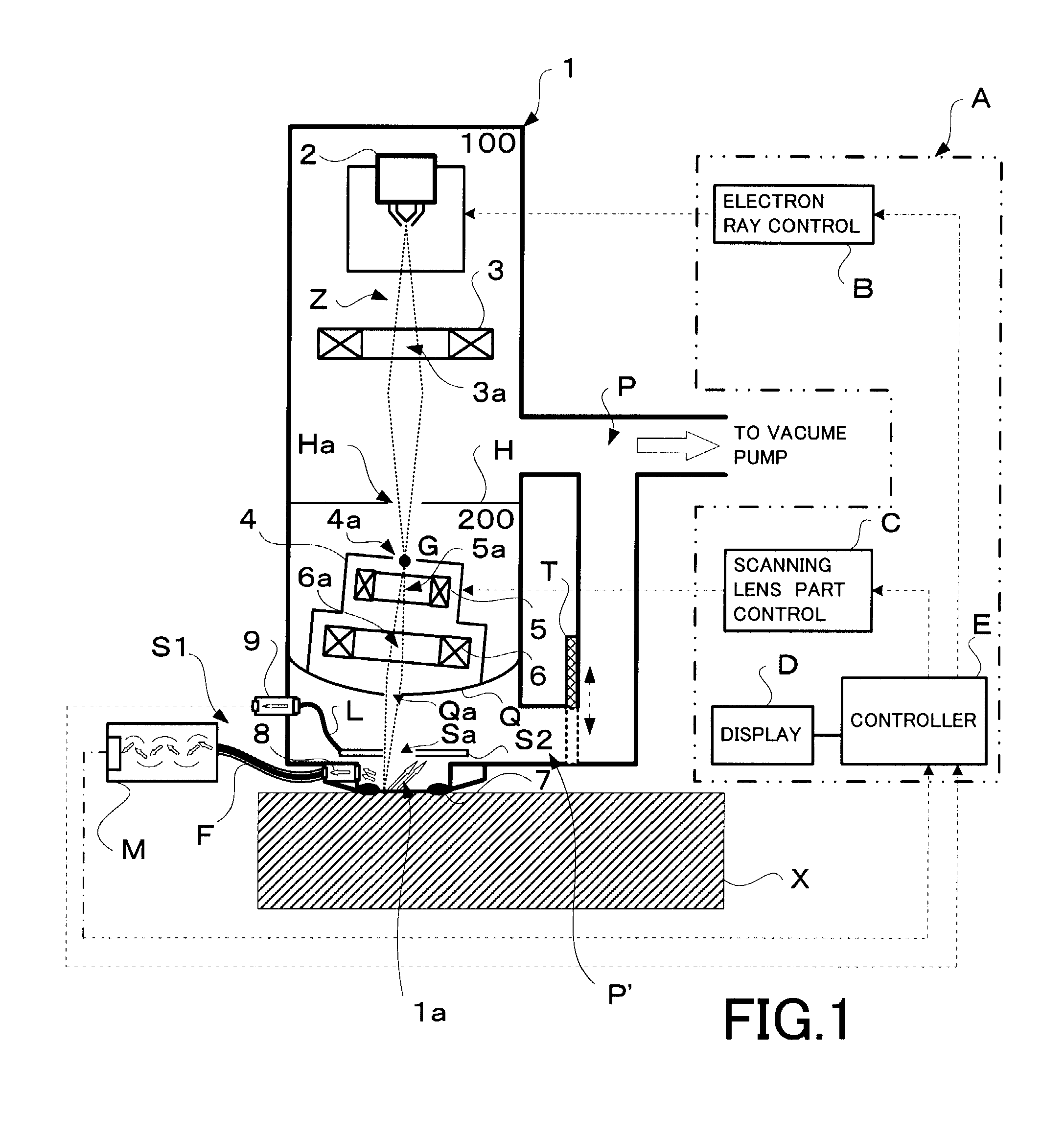
[0022]FIG. 1 is a conceptual diagram illustrating one embodiment of a general configuration of a scanning electron microscope according to the present invention. The scanning electron microscope shown in FIG. 1 can be roughly divided into a lens barrel 1 constituting a microscope main unit for irradiating electron rays Z onto an observation object (sample) X, scanning the observation object X with the electron rays Z and so on, a secondary electron detector S1 and a reflected electron detector S2 provided separately and independently from the lens barrel 1 for detecting secondary electrons and reflected electrons, respectively, emitted from the observation object X in response to the irradiation of the electron rays Z, and a control device group A for performing electron ray control operations such as the emission of the electron rays Z and scanning in th...


PUM


Abstract

A seal member to be contacted with an observation object is provided at an open end of a lens barrel so that the observation object can be attracted to the lens barrel via the seal member and fixed in direct and close contact with the lens barrel when a vacuum is created in the lens barrel by a vacuum pump. In other words, instead of providing a sample chamber, the observation object is fixed in close contact with the lens barrel to prevent relative movement therebetween by a suction force even without a sample chamber. In this configuration, the interior of the lens barrel can be maintained in a vacuum state despite the absence of a sample chamber and no adverse effect occurs during observation because the lens barrel and the observation object are not moved relative to each other by vibration.

Description

BACKGROUND[0001]The present invention relates to a scanning electron microscope which allows observation of a sample by scanning the sample in synchronization with emission of electron rays. In particular, the present invention relates to a scanning electron microscope with which an observation object which is conventionally too large to fit in a sample chamber and therefore needs preliminary processing can be directly observed without any preliminary processing.[0002]A scanning electron microscope (SEM) is conventionally known which enables the user to observe the composition or surface unevenness of a sample by converging electron rays emitted from an electron gun in a stepwise fashion with at least one electron lens to form a finely-focused flux of electrons, directing the formed convergent electron rays (electron beams) onto a sample as an observation object to scan the sample, and detecting secondary electrons and reflected electrons emitted from the sample in response to the s...

Claims


Application Information

Patent Timeline
Patent Type & Authority Applications(United States)
IPC IPC(8): H01J37/28
CPCH01J37/16H01J2237/2006H01J2237/162H01J37/18
Inventor MATSUMOTO, KENJI
Owner HONDA MOTOR CO LTD
Why Eureka
Try Eureka