Mesh and method of observing rubber slice technical field

a technology of rubber slice and mesh, which is applied in the direction of liquid/fluent solid measurement, instruments, machines/engines, etc., can solve the problems of almost impossible to stretch a conventional mesh to which the sample is fixed, and impossible to observe the rubber slice in a stretched state, etc., and achieves the effect of convenient handling of the mesh

Inactive Publication Date: 2010-03-09
SUMITOMO RUBBER IND LTD
View PDF4 Cites 2 Cited by
  • Summary
  • Abstract
  • Description
  • Claims
  • Application Information

AI Technical Summary

Benefits of technology

[0011]In the above-described construction, the slit for opening use is formed by cutting the mesh in the required length from a portion of its periphery disposed between its left and right to-be-fixed portions in the direction orthogonal to the stretch direction or the direction inclined thereto. Therefore by separating the sample holder separation portions to which the left and right sides of the mesh have been fixed respectively from each other and moving the sample holder separation portions in the stretch direction, the mesh is uniformly stretched in the stretch direction while the slits for opening use is being opened, and the rubber slice fixed to the mesh is also stretched, as the mesh is stretched. Accordingly by only moving the sample holder separation portions to which the left and right sides of the mesh have been fixed in the stretch direction, it is possible to stretch the rubber slice at any desired degree of stretching and directly observe the state of the rubber slice at any desired degree of stretching. Thereby it is possible to observe the change of the state (morphology change) of the rubber slice in the stretch process.
[0017]As described above, when the slit for dividing use is formed in the direction orthogonal to the stretch direction or the direction inclined thereto, it is possible to stretch the rubber slice in the stretch direction by dividing the mesh. But to form the slit for dividing use in the direction orthogonal to the stretch direction is simplest and allows the rubber slice to be uniformly stretched in the stretch direction.
[0022]In the case of the mesh having the narrow-groove-shaped opening formed therethrough, by forming one slit for opening use at each of upper and lower positions of the mesh sandwiching the narrow-groove-shaped opening therebetween, it is possible to greatly extend the mesh in the stretch direction.
[0030]It is preferable to form the slit for opening use of the mesh and the slit for dividing use thereof used in the method of the third and fourth inventions of observing the rubber slice by cutting the mesh with razor, surgical knife, cutter or the like after the rubber slice is fixed to the upper surface of the central portion of the mesh. Thereby it is easy to handle the mesh because the mesh is not divided into a large number of pieces before the mesh is stretched and possible to fix the rubber slice to the mesh in a stable state.
[0031]As described above, according to the first invention, the slit for opening use is formed by cutting the mesh in the required length from the outer edge thereof disposed between its left and right to-be-fixed portions in the direction orthogonal to the stretch direction or the direction inclined thereto. Therefore by moving the sample holder separation portions to which the left and right sides of the mesh have been fixed respectively in the stretch direction, the mesh is uniformly stretched in the stretch direction while the slits for opening use is being opened, and the rubber slice fixed to the mesh is also stretched, as the mesh is stretched. Accordingly by moving the sample holder separation portions to which the left and right sides of the mesh have been fixed respectively in the stretch direction, it is possible to stretch the rubber slice at any desired degree of stretching and directly observe the state of the rubber slice, as the third invention provides.
[0032]According to the second invention, the mesh has the slit for dividing use formed from a portion of its periphery disposed between the left and right to-be-fixed portions of the mesh to be fixed to the sample holder separation portions respectively toward the rubber slice-placing position of the mesh in the direction orthogonal to the stretch direction of the rubber slice or the direction inclined thereto. Therefore by moving the sample holder separation portions to which the left and right sides of the mesh have been fixed respectively in the stretch direction, the mesh is divided into the left and right parts in the stretch direction. The rubber slice fixed to the left and right parts of the mesh is stretched uniformly in the stretch direction owing to the division of the mesh and the move-away of the left and right parts thereof. Thus by only moving the sample holder separation portions to which the left and right sides of the mesh have been fixed respectively in the stretch direction, it is possible to stretch the rubber slice at any desired degree of stretching without deforming the mesh and directly observe the rubber slice in the stretch process.

Problems solved by technology

It is almost impossible to stretch a conventional mesh to which the sample is fixed, which makes it impossible to observe the rubber slice in a stretched state.

Method used


Image

  • Mesh and method of observing rubber slice technical field
  • Mesh and method of observing rubber slice technical field
  • Mesh and method of observing rubber slice technical field

Examples


first embodiment

[0046]FIGS. 1 through 5 show the present invention.

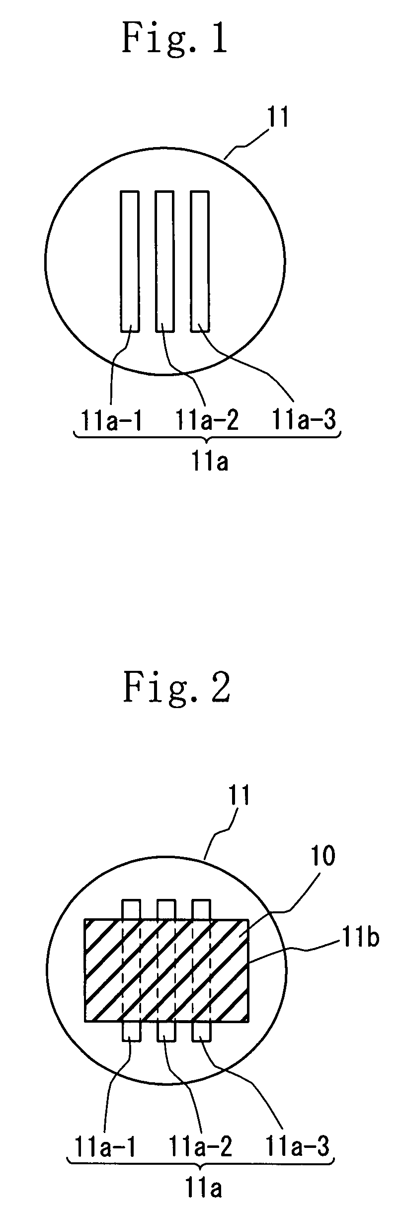
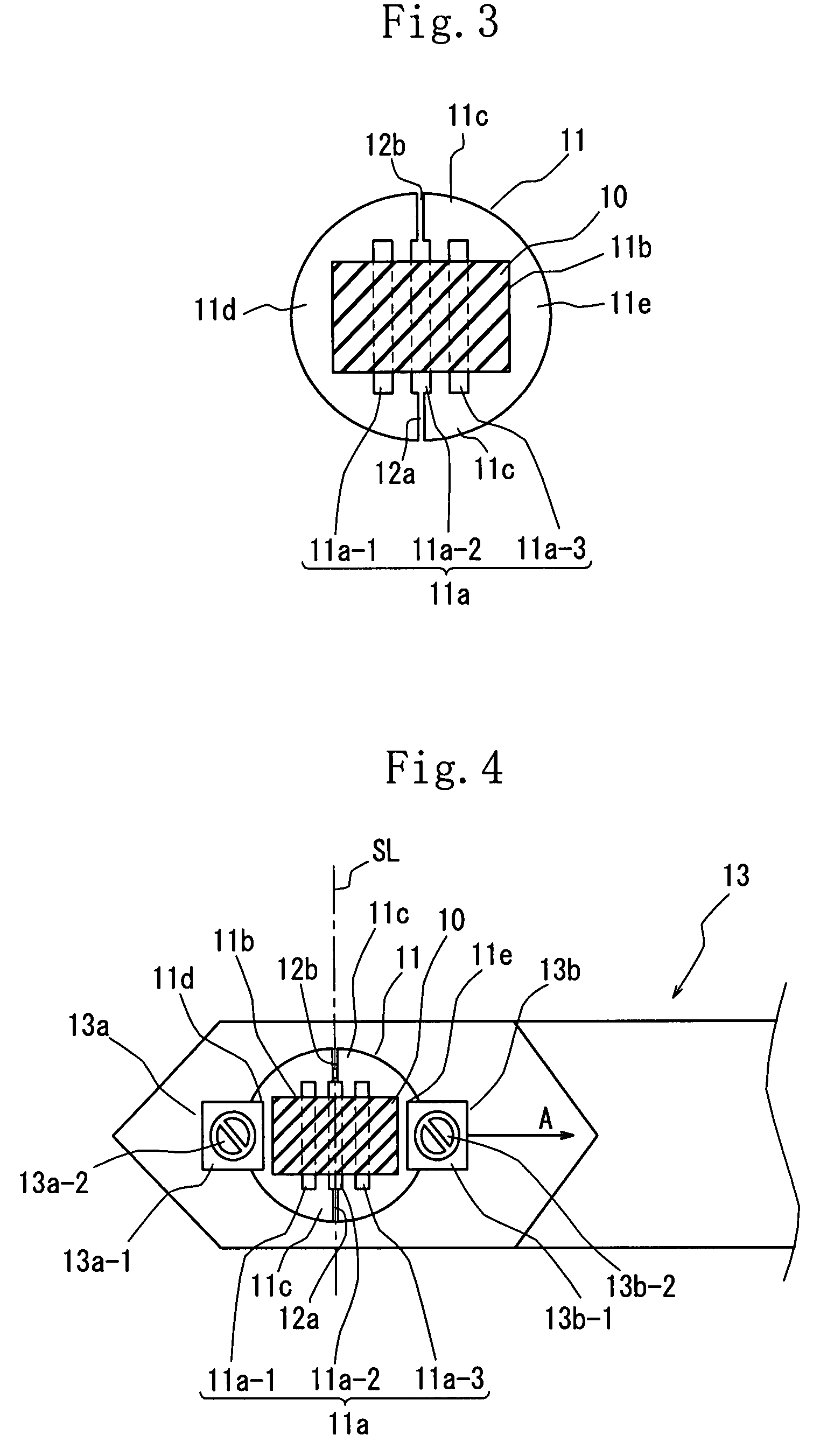
[0047]A mesh 11 of the first embodiment has narrow groove-shaped openings 11a in a placing region 11b where a rubber slice 10 is placed and slits 12a, 12b for dividing use communicating with the narrow groove-shaped openings 11a.

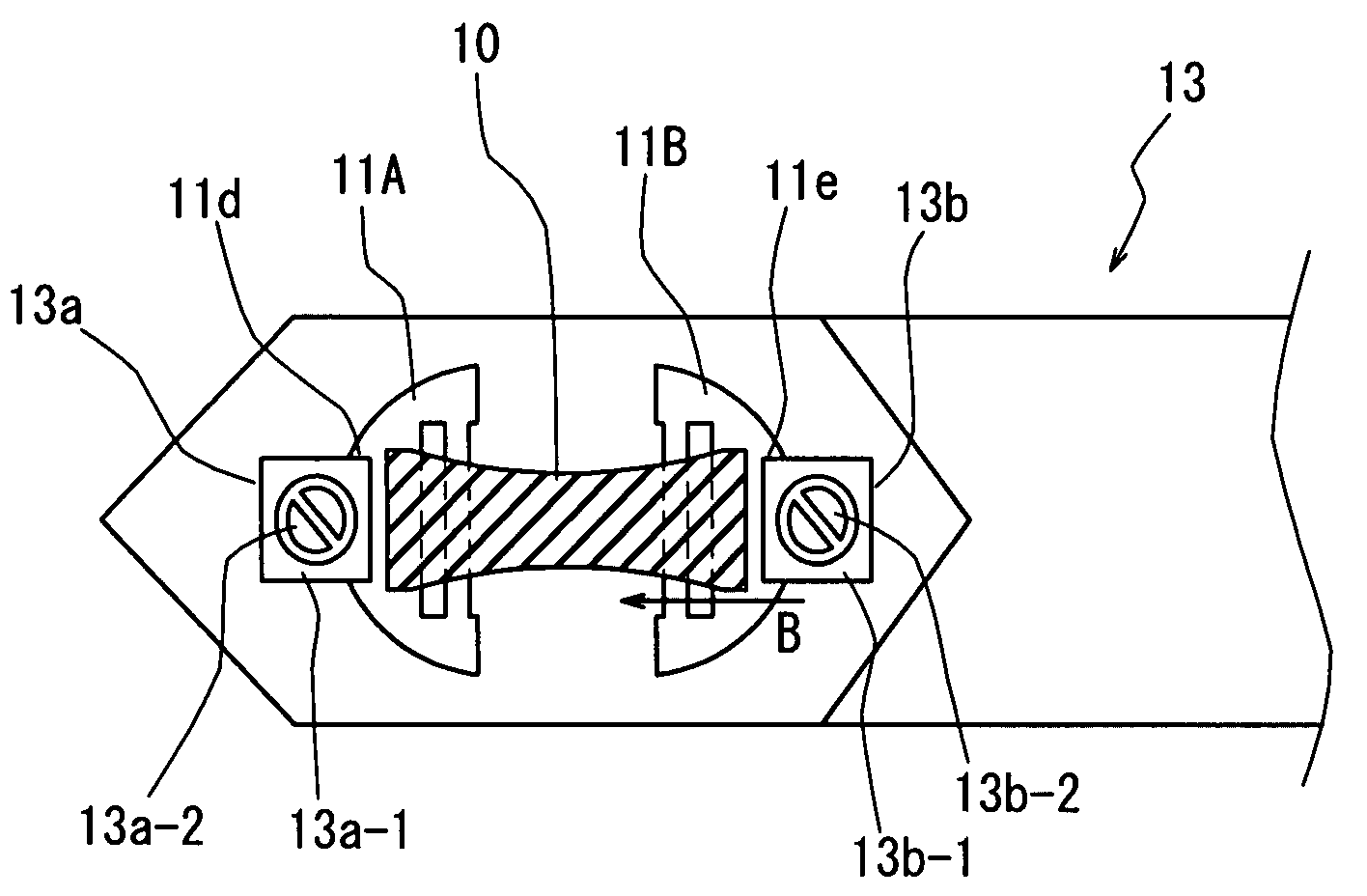
[0048]That is, after the rubber slice 10 to be used as a sample shown in FIG. 2 is fixed to the mesh-placing region 11b disposed on an upper surface of the center of the mesh 11 which has three narrow groove-shaped openings 11a at the center thereof, as shown in FIGS. 3 and 4, the slits 12a, 12b for dividing use are sequentially formed on the mesh 11 by using a cutting blade (razor in the first embodiment).

[0049]Making detailed description, initially the thinned rubber slice 10 (1 mm (length)×2 mm (width)×200 nm (thickness)) is made from a rubber composition having components mixed at ratios shown in table 1 by using a microtome (not shown, commercial name: Ultramicrotome EM VC6, produced by LEICA Inc.).

[00...

second embodiment

[0071]FIG. 7 shows a

[0072]A mesh 14 of the second embodiment has one narrow groove-shaped opening 14a formed by cutting a lower side of a peripheral frame 14c. One slit 15 for dividing use is formed at an upper side of the peripheral frame 14c to form the division line SL of the narrow groove-shaped opening 14a and the slit 15 for dividing use.

[0073]After left and right sides 14d, 14e of the mesh 14 are fixed to the sample holder separation portions 13a, 13b, respectively with the rubber slice 10 fixed to the mesh 14, the slit 15 for dividing use is formed in the direction orthogonal to the stretch direction (left-to-right direction).

[0074]In the second embodiment, by the movement of the sample holder separation portion 13b in the stretch direction, the mesh 14 is divided into left and right parts, and without deforming the mesh 14, the rubber slice 10 can be stretched uniformly in the stretch direction. Therefore similarly to the first embodiment, the rubber slice 10 in the stretch...

third embodiment

[0075]FIG. 8 shows a

[0076]In a mesh 16 of the third embodiment, slits 17a, 17b, and 17c for opening use are alternately formed at upper and lower positions of a peripheral frame 16c surrounding a narrow groove-shaped opening 16a in the direction orthogonal to the stretch direction (left-to-right direction) of the rubber slice 10 to such an extent that the slits 17a, 17b, and 17c for opening use do not communicate with the narrow groove-shaped opening 16a.

[0077]The slits 17a, 17b, and 17c for opening use are formed after the left and right sides 16d, 16e of the mesh 16 are fixed to the sample holder separation portions 13a, 13b respectively with the rubber slice 10 fixed to the mesh 16. Other constructions of the third embodiment are similar to those of the first embodiment.

[0078]According to the above-described construction, the mesh 11 has the slits 17a, 17b, and 17c for opening use formed vertically and alternately on the peripheral frame 16c disposed between the left and right t...


PUM


Abstract

Left and right sides of the mesh sandwiching the placing region therebetween are set as left and right to-be-fixed portions to be fixed to sample holder separation portions respectively to be moved in a stretch direction. A slit for dividing use is formed from a portion of the periphery of the mesh disposed between the left and right to-be-fixed portions thereof toward the rubber slice-placing position of the mesh in a direction orthogonal to the stretch direction of the rubber slice or a direction inclined thereto. When the to-be-fixed portions are moved in a separation direction by moving the sample holder separation portions, the mesh is divided into left and right parts by the slit for dividing use so that the rubber slice fixed to the left and right sides of the mesh is stretched.

Description

[0001]This nonprovisional application claims priority under 35 U.S.C. § 119(a) on Patent Application No(s). 2006-275543 filed in Japan on Oct. 6, 2006, the entire contents of which are hereby incorporated by reference.FIELD OF THE INVENTION[0002]The present invention relates to a mesh for holding a sample when the sample is observed by a microscope and a method of observing a rubber slice used as the sample by holding the rubber slice by the mesh, and more particularly to a mesh capable of observing a rubber slice in a stretch process and the rubber slice both in the stretch process and a contraction process.[0003]In observing a sample with a microscope such as a transmissive electron microscope (TEM), after the sample is thinned with a cutting device, the thinned sample is fixed to a sample-supporting material called a mesh. After the mesh is fixed to the exclusive sample holder, the sample is observed.[0004]Normally, a disk-shaped mesh 1 having a diameter of about 3 mm has reticul...

Claims


Application Information

Patent Timeline
Patent Type & Authority Patents(United States)
IPC IPC(8): G21K5/10
CPCG01N3/04G01N3/08H01J37/20H01J37/26H01J2237/2007H01J2237/2062H01J2237/28
Inventor KISHIMOTO, HIROYUKINAKAMAE, HIROFUMIKOTANI, MARINADOHI, HIDEHIKOJINNAI, HIROSHIKANEKO, TAKESHI
Owner SUMITOMO RUBBER IND LTD
Why Eureka
Try Eureka