Clamping device

Inactive Publication Date: 2012-06-14
HYUNDAI MOTOR CO LTD
View PDF5 Cites 16 Cited by
  • Summary
  • Abstract
  • Description
  • Claims
  • Application Information

AI Technical Summary

Benefits of technology

[0011]The present invention has been made in an effort to reduce the overall size of a clamping device by using a motor as a driving source and maintaining a clamping force applied to a panel consistently through accurate stroke control by incorporating into the device a worm gear.
[0012]Further, the present invention provides a clamping device which reduces manufacturing costs through simplification of the overall configuration and layout by removing the cylinder and hinge structure and reducing weight due to size reduction.

Problems solved by technology

However, since the known clamping device uses the actuating cylinder 5 as a power source, the layout of connection pipes installed to supply the air pressure or oil pressure for performing the actuating of the actuating cylinder 5 becomes complicated and it is difficult to control the actuating pressure, and as a result, the clamping force of the clamping device is not constant.
Furthermore, as a result, spatial utilization of a workplace deteriorates.

Method used


Image

  • Clamping device
  • Clamping device
  • Clamping device

Examples


Embodiment Construction

[0040]An exemplary embodiment of the present invention will hereinafter be described in detail with reference to the accompanying drawings.

[0041]Exemplary embodiments described in the present specification and a configuration shown in the drawings are just the most preferable exemplary embodiment of the present invention, but are not limited to the spirit and scope of the present invention. Therefore, it should be understood that there may be various equivalents and modifications capable of replacing them at the time of filing of the present application.

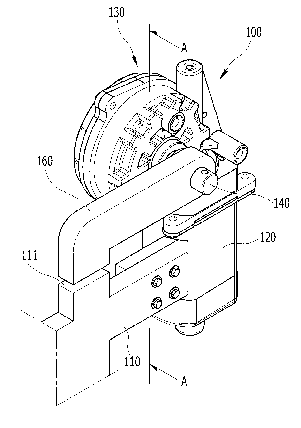
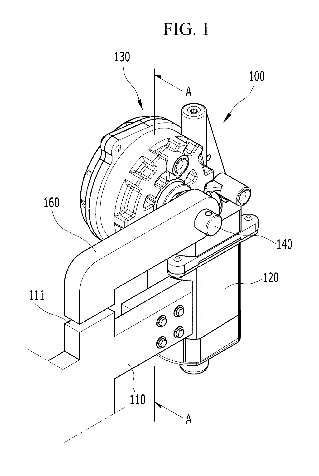
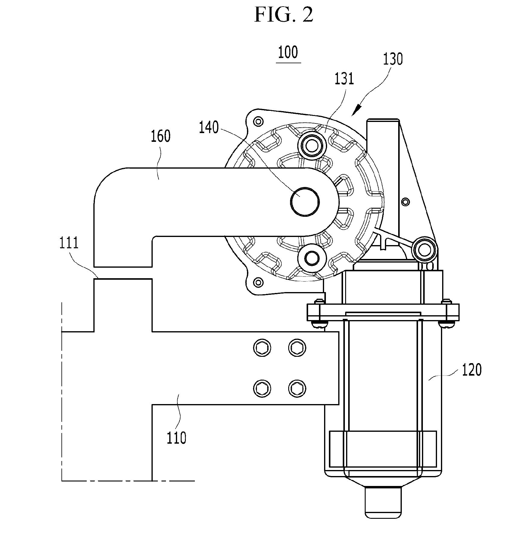
[0042]FIG. 1 is a perspective view of a clamping device according to an exemplary embodiment of the present invention, FIG. 2 is a front view of a clamping device according to an exemplary embodiment of the present invention, and FIG. 3 is a cross-sectional view take along line A-A of FIG. 1.

[0043]A clamping device 100 according to an exemplary embodiment of the present invention, which is used to clamp and fix a panel, includes a lo...


PUM


Abstract

Disclosed is a clamping device which reduces the overall size typical clamping devices used for similar operations by implementing a motor as a driving source and maintaining a clamping force applied to a panel constantly through accurate stroke control by incorporating a worm gear. More specifically, the clamping device includes a locator on which a panel is seated and a driving motor incorporated into a portion of the locator. A gear box rotates a rotation rod by receiving a rotational force from the driving motor and a clamper connected with the rotation rod, clamps the panel seated on the locator.

Description

CROSS-REFERENCE TO RELATED APPLICATION[0001]This application claims priority to and the benefit of Korean Patent Application No. 10-2010-0124905 filed in the Korean Intellectual Property Office on Dec. 8, 2010, the entire contents of which are incorporated herein by reference.BACKGROUND OF THE INVENTION[0002](a) Field of the Invention[0003]The present invention relates to a clamping device, and more particularly, to a motor driven clamping device capable of reducing an overall size of the clamping device by using a motor as a driving source and maintaining a clamping force applied to a panel consistently through accurate stroke control by incorporating a worm gear.[0004](b) Description of the Related Art[0005]In general, a clamping device is used to fix a material panel so as to prevent the material panel from being moved at the time of performing processing operations such as cutting, plating, welding, and the like of the material panel. The clamping force or restriction portion of...

Claims


Application Information

Patent Timeline
IPC IPC(8): B25B5/06
CPCB25B5/06B25B5/04
Inventor CHOI, JEONGHOJEONG, IN HO
Owner HYUNDAI MOTOR CO LTD
Why Eureka
Try Eureka