Compact System of Multi-Beam Antennas

Inactive Publication Date: 2012-06-14
THOMSON LICENSING SA
View PDF10 Cites 0 Cited by
  • Summary
  • Abstract
  • Description
  • Claims
  • Application Information

AI Technical Summary

Benefits of technology

[0008]The present patent application relates to an improvement of this network type enabling a better directivity of radiating beams to be obtained and to produce, as a result, a highly directive system of multi-beam antennas.

Problems solved by technology

Up until now, the use of directive antennas has remained limited to applications operating at very high frequencies, often with fixed beams, and do not have size constraints such as those of radar applications or satellite applications.
Thus, for these application types, antenna devices are known that generate multiple beams but are composed of numerous modules that are often complex and costly.
However, this method has a certain number of significant disadvantages.

Method used


Image

  • Compact System of Multi-Beam Antennas
  • Compact System of Multi-Beam Antennas
  • Compact System of Multi-Beam Antennas

Examples


first embodiment

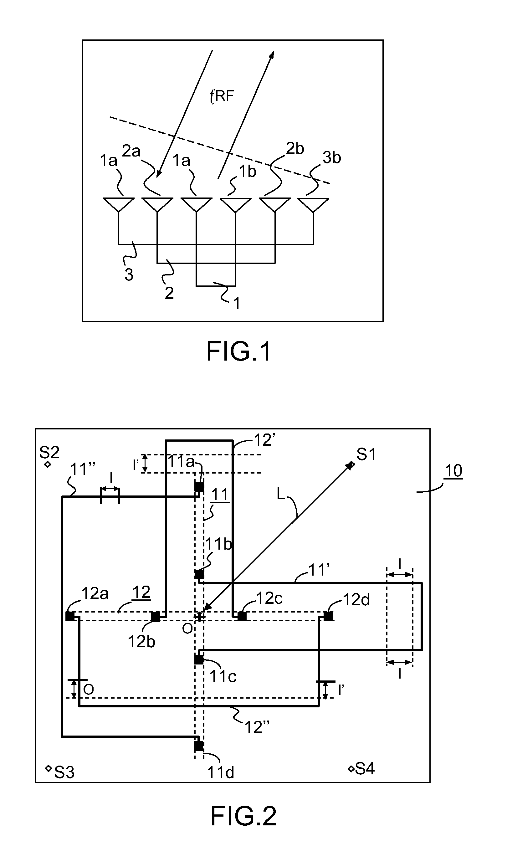
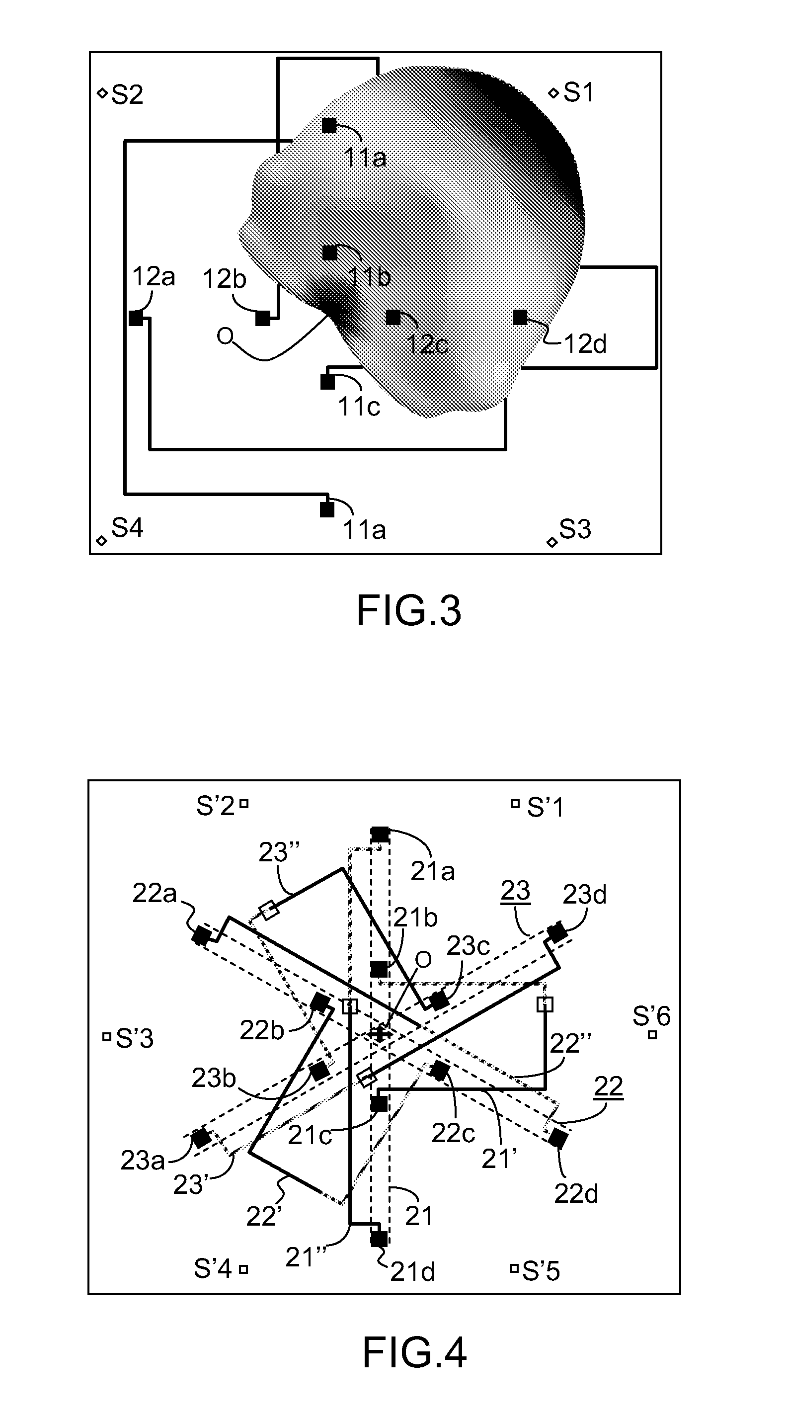
[0028]A description will first be given, with reference to FIGS. 2, and 3 of a compact multi-beam antennas system in accordance with the present invention.

[0029]On a substrate 10 of large dimensions provided with a ground plane, an antenna system has thus been produced comprising two Van Atta type monopole networks and several sources positioned symmetrically around the networks. The monopoles are positioned in the field close to sources, as will be explained in more detail hereafter. In the embodiment of FIG. 2, the substrate 10 is a square substrate having a ground plane of dimensions 250×250 mm. It is produced preferably using FR4 type (εr=4.4 and tan(delta)=0.02) multi-layer standard substrate. The substrate has a thickness of 1.4 mm. As shown in FIG. 2, on the substrate 10 two retro-directive type networks have been produced, each constituted of four quarter wave monopoles spaced at a distance d that, in the embodiment shown, is selected to be equal to 0.2 λ0 with λ0 the wavele...

third embodiment

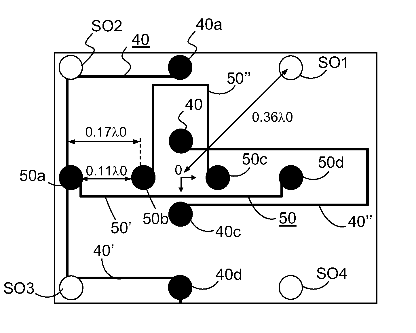
[0041]the present invention will now be described with reference to FIGS. 6 to 8, enabling a more compact system of multi-beam antennas to be obtained and having an improved directivity. In the case of the embodiment of FIG. 6, two co-located retro-directive networks 40 and 50 are used. The first network comprises quarter wave monopoles 40a, 40b, 40c and 40d connected two by two, as in the preceding embodiments, via power supply lines 40′ or 40″ produced in microstrip technology and having identical electrical lengths. Likewise, the second network 50 is constituted by quarter wave monopoles 50a, 50b, 50c and 50d connected two by two via power supply lines 50′ and 50″ in microstrip technology and having identical electrical lengths. The two networks are perpendicular to one another, in the embodiment shown. They are lit by four sources SO1, SO2, SO3 and SO4 arranged symmetrically with respect to the two networks.

[0042]In accordance with the embodiment of FIG. 6, the network monopoles...


PUM


Abstract

The present invention relates to a system of multi-beam antennas comprising M radiating sources and P networks of N radiating elements, P being greater than 1 and N being an even whole number, the network elements being connected two by two via transmission lines of the same electrical length. In addition, the P networks are co-located at the centre of each network, the M radiating sources are each positioned at a distance Li from said centre, the distance Li being strictly less than the distance of the field called the far field and i varying from 1 to M.This system can be used with MIMO type devices.

Description

[0001]The present invention relates to a compact multi-beam antenna system, particularly a multi-beam antenna system that can be used in the context of wireless communications, more particularly in wireless domestic networks in which the conditions for propagation of electromagnetic waves are very penalising due to multiple paths.BACKGROUND OF THE INVENTION[0002]For emerging applications such as wireless domestic networks, intelligent networks or similar type networks, the use of directive antennas, that is antennas able to focus the radiated power in a particular direction of the space are proving particularly attractive. However, the laws of physics impose a minimum size for antennas, this size being all the more significant as the antenna is more directive or as its operating frequency is low.[0003]Up until now, the use of directive antennas has remained limited to applications operating at very high frequencies, often with fixed beams, and do not have size constraints such as th...

Claims


Application Information

Patent Timeline
IPC IPC(8): H01Q21/00H01Q13/02H01Q13/10
CPCH01Q3/2647H01Q25/002H01Q21/28H01Q19/32H01Q21/06
Inventor PINTOS, JEAN-FRANCOISMINARD, PHILIPPELOUZIR, ALILO HINE TONG, DOMINIQUE
Owner THOMSON LICENSING SA
Why Eureka
Try Eureka